The semi-diameter of some radially symetric surface is set to “automatic”. From the Zemax help, I understood that the diameter is adjusted so that no rays are clipped.I´m confused by the mechanical semi-diameter, which in some cases takes a smaller value than the semi-diameter. See picture.
Shouldn´t the mechanical semi-diameter always be larger than the semi-diameter? Why isn´t it so, when all the values are set to automatic?
Best answer by David.Nguyen
Hi @Jonasz,
When you start with a new design, I wouldn’t setup apertures unless you have a good reason to do so. That way, the surfaces will adjust their sizes automatically. Apertures are mostly useful at a later point in the design phase where you start to account for mechanical constraints as you described.
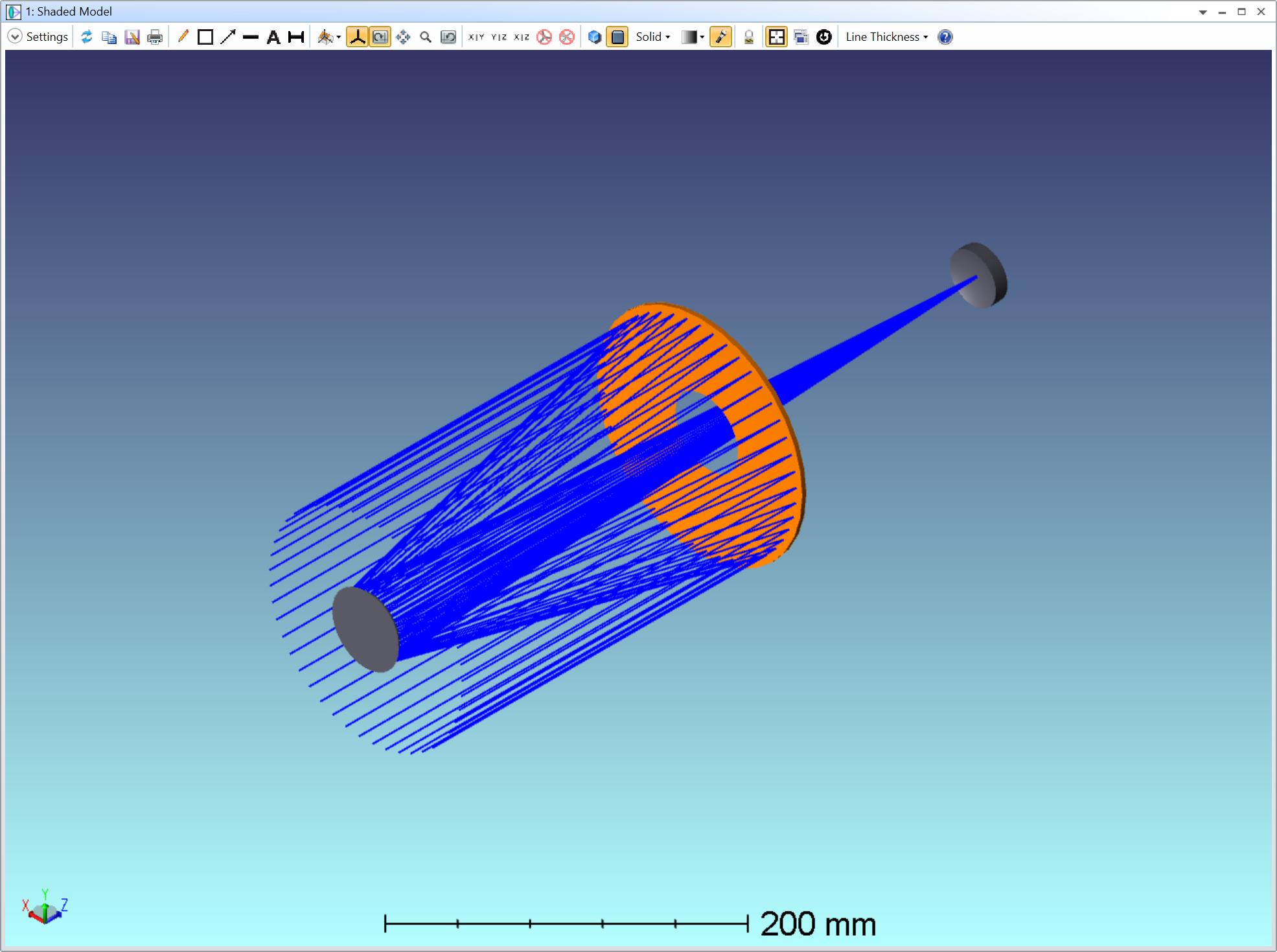
I wouldn’t say these two concepts are redundant, even though I can see why calling both “apertures” can be confusing. An aperture applies to any surface, and can have many different shapes (not necessarily a circular opening). On the other hand, the aperture stop is often assumed to be a circular opening (it can be tweaked with vignetting factors, but not to the same extent as apertures I believe). Perhaps you can have a look at the telescope sample file: {Your_Documents}\Zemax\Samples\Sequential\Telescopes\Cassegrain-type Ritchey Chretien.zos.
Here is the Shaded Model of that sample file with the stop surface in orange:
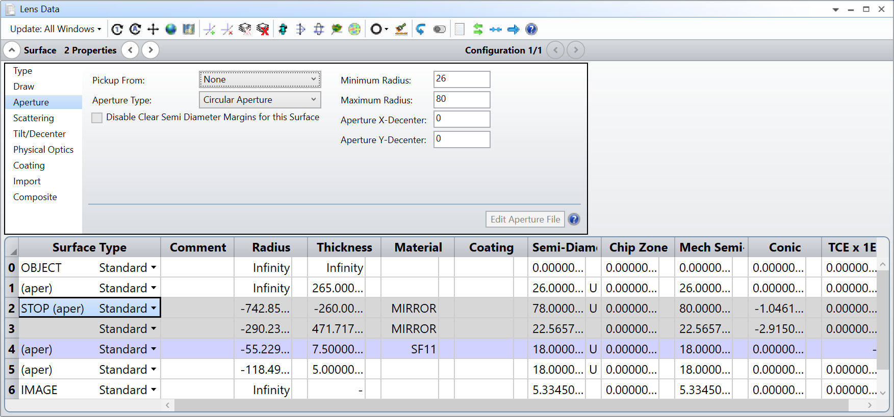
In the Lens Data Editor you can see they applied an annular aperture:
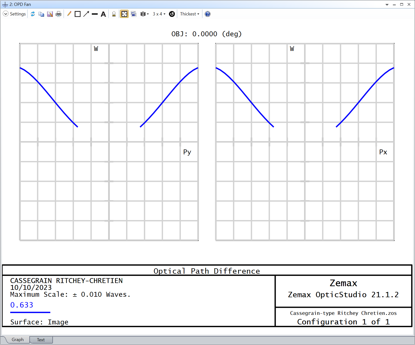
Whereas the aperture stop definition is Entrance Pupil Diameter, and is set to 150.0 mm. The rays that fall at the center of the annulus are clipped, and if you look at the OPD Fan, you see that its missing the corresponding fraction of rays:
Does that help understanding why both concepts are present?
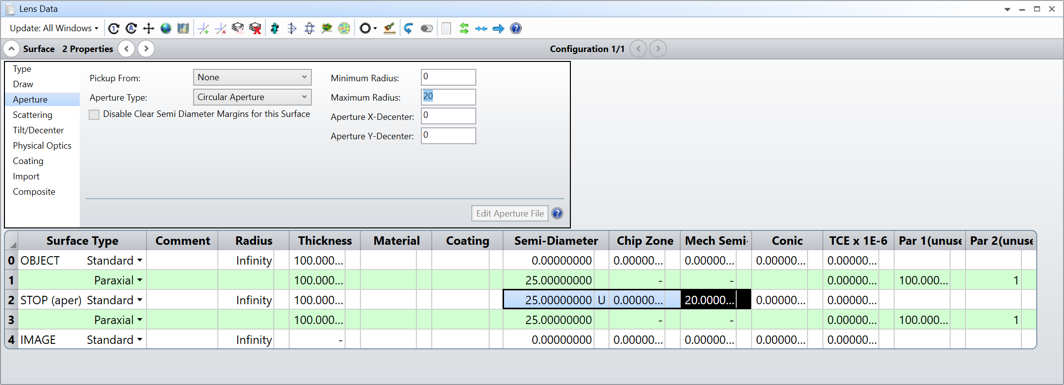
We can see that there’s an aperture on your surfaces (because its written aper on the left-hand side of the Surface Type). I’m guessing this aperture is limiting the Mech Semi-Dia.
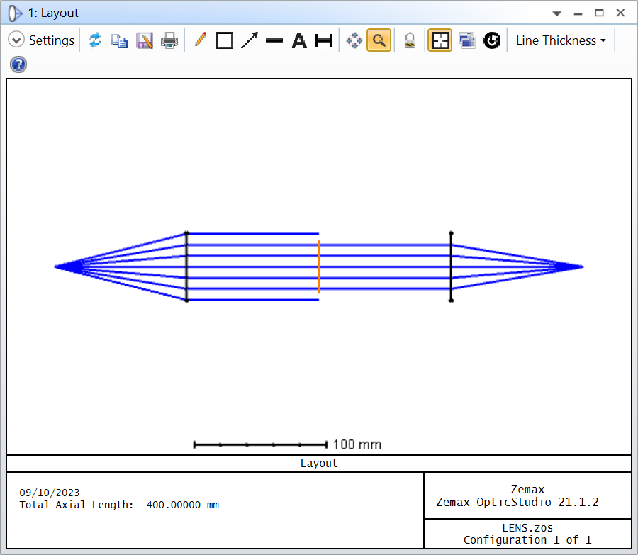
Below is an example where I reproduced the behaviour. My Semi-Diameter is 25 mm at the stop, but the Mech Semi-Diameter is 20 mm, limited by the Aperture settings:
So, the rays are traced to fill the surface stop (I’m using Float By Stop Size definition), but they are clipped by the aperture on the surface stop.
Does that make sense? I don’t know if that’s the same in your file, but have a look at the aperture setting in your surfaces.
It seems then that some of these variables are redundant to each other. As a design good practice, is it recommended to assign “aper” to all the surfaces?
It seems that limiting it to the aperture stop should be enough. The rest of the diameters could be let free and would be fixed in the last stage where, for example, one picks a common mechanical semi diameter to all components for an easy assembly.
When you start with a new design, I wouldn’t setup apertures unless you have a good reason to do so. That way, the surfaces will adjust their sizes automatically. Apertures are mostly useful at a later point in the design phase where you start to account for mechanical constraints as you described.
I wouldn’t say these two concepts are redundant, even though I can see why calling both “apertures” can be confusing. An aperture applies to any surface, and can have many different shapes (not necessarily a circular opening). On the other hand, the aperture stop is often assumed to be a circular opening (it can be tweaked with vignetting factors, but not to the same extent as apertures I believe). Perhaps you can have a look at the telescope sample file: {Your_Documents}\Zemax\Samples\Sequential\Telescopes\Cassegrain-type Ritchey Chretien.zos.
Here is the Shaded Model of that sample file with the stop surface in orange:
In the Lens Data Editor you can see they applied an annular aperture:
Whereas the aperture stop definition is Entrance Pupil Diameter, and is set to 150.0 mm. The rays that fall at the center of the annulus are clipped, and if you look at the OPD Fan, you see that its missing the corresponding fraction of rays:
Does that help understanding why both concepts are present?