Hi everyone,
In the spot diagram, how it automatic calculate 5 fields? And how it get the five coordinates on the IMA?
Thanks,
Xiaolei


Hi everyone,
In the spot diagram, how it automatic calculate 5 fields? And how it get the five coordinates on the IMA?
Thanks,
Xiaolei
Best answer by David.Nguyen
Hi Xiaoleiwang,
Sorry if my first answer wasn’t clear. Let me try to rephrase it.
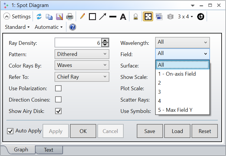
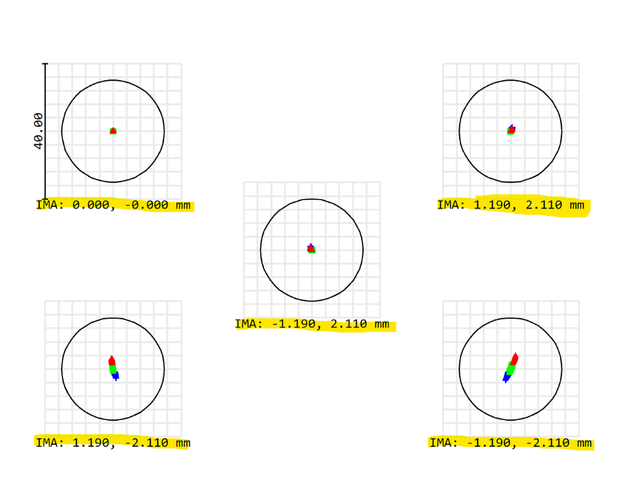
How the IMA coordinate you see in the Spot Diagram is calculated depends on the the setting you chose under Refer To, see my screenshot below from the Double Gauss 28 degree field sample file:
The reference chosen is also written at the bottom, in the footer of the Spot Diagram.
If you have chosen the default Chief Ray, then OpticStudio will trace a Chief ray at the primary wavelength for each field you have defined and the IMA coordinate is going to be the intersection of this chief ray with the Surface specified in the setting (by default: the Image surface).
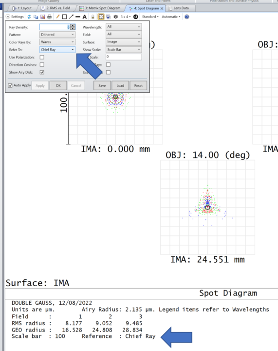
You can verify what I’m saying with a Analyze..Rays & Spot..Single Ray Trace. If I use the same file as above (Double Gauss 28 degree field), and perform a single ray trace of a chief ray (Px and Py = 0) at the primary wavelength (2) for Field 3, this is the result:
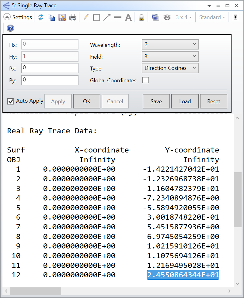
As you can see, the Y-coordinate is 24.551 mm as in my first screenshot for the third field (the one at the bottom). If you change the Refer To setting, then the IMA coordinate is calculated differently, and you’ll find more details in the Help File (but let me know if you have questions about that):
Refer To The spot diagrams by default are referenced to the real chief ray. The RMS and GEO spot radii listed at the bottom of the diagram (and defined in the discussion section) are calculated assuming the chief ray is the "zero aberration" point. However, this option allows selection of other reference points. The centroid is defined by the average position of the rays traced. The middle is defined so that the maximum ray errors are equal in the plus and minus x and y directions. The vertex is defined by the local coordinates 0,0 on the selected surface. If the system is in afocal mode, the chief ray reference will be used instead of the vertex reference.
Now, if you want the IMA coordinates to be different (assuming we will be using Refer To: Chief Ray). Then, you need to modify your Fields in the System Explorer. This is what I would recommend:
Let me know if this answer is clearer and if you have any other question.
Take care,
David
Enter your E-mail address. We'll send you an e-mail with instructions to reset your password.
Do not provide any information or data that is restricted by applicable law, including by the People’s Republic of China’s Cybersecurity and Data Security Laws ( e.g., Important Data, National Core Data, etc.).
不要提供任何受适用法律,包括中华人民共和国的网络安全和数据安全法限制的信息或数据(如重要数据、国家核心数据等)。