
Hello Experts,

I am trying to compare a Shack Hartmann wavefront measurement with my Zemax wavefront map.

Image depicting the measurement setup from the website of the Shack Hartmann Sensor manufacturer (Optocraft)

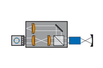
The Shack Hartmann setup I have is a double pass system where the objective is illuminated with a plane wave output from the sensor with a spherical mirror placed below the lens under test. The rays from the mirror are reflected back through the lens under test and then through the internal optical system of the measurement setup to the sensor. I am trying to model the double pass system so that i can replicate the setup as closely as possible. 
What I have done so far is:
1. Use the “make double pass” replacing the image surface with a spherical mirror. This makes the first surface of the lens under test as the new “image” surface (after making double pass the first surface is also the last surface)
2. I use the knowledge base article  “https://optics.ansys.com/hc/en-us/articles/42661811084691-Display-pupils-on-a-layout-plot” to create exit pupil of this new double pass system.

  1. Evaluate the wavefront map on the exit pupil.

The issue i am facing is that the measuremetn are far off from the model wavefront.

I have tried to make sure the wavelength is correct and I have tried multiple settings in “Aperture”, “Advanced” and “ray aiming” from the System Explorer but all combinations led to results that were not even close to the measured values.

I am writing this to ask if there is something obviously clear to the experts which i cannot see or mistakenly ignored?

Any help is appreciated. Thank you in advance.


Amit


Hi Amit,

When using the Make Double Pass tool, OpticStudio does nothing to try to change the Stop of the system, so I would take extra care in ensuring the Stop is truly correct in your system; if you have a high amount of aberrations in your test system, then placing the Stop on the front half vs the back half of the double pass system will change the results.

Also, by default, OpticStudio has the Reference OPD (System Explorer > Advanced > Reference OPD) set to Exit Pupil, which uses the location of the Exit Pupil in image space to calculate the wavefront.  This calculation is the difference of the aberrated wavefront from the perfect sphere which will provide no ray aberrations.  If the Stop location is not correct in your system, the Exit Pupil will not be correct.  Using one of the other methods (Infinite, Absolute or Absolute2) might be more appropriate.

Finally, according to your diagram, you’re using collimated light (bottom left) to test the concave optic (bottom right), turning your imaging system into a double pass, and then having collimated light back out (bottom left again).  If this is the test setup, then you should use Afocal Image Space (System Explorer > Aperture > Afocal Image Space) to change the OPD reference from a spherical wave to a plane wave. 


@MichaelH Hello Michael,

When i make the model double pass, i also changed the stop position to be in the second pass. IN the first pass the stop surface was simply removed and the distance between the STOP and the previous optical surface were added so that the distance to the next optical surface remains constant.

I also use the Afocal image space and Absolute2 for reference OPD setting.

Also, I am using the collimating light to test the lens (which is shown in blue, not the mirror). The mirror just enables the double pass system. But yes, i use the collimated light to illuminate the lens under test which focuses the light on the center of curvature of a spherical mirror and then reflects the light back (essentially forming a collimated beam with the abberations of course from the lens under test).

With all these settings my results are still different from measurement which leads me to believe a discrepacny between the lens under test and its ZEMAX model. Do you think this is a correct assumption?


Regards, Amit