Solved

Path Analysis Loss of Power and Atmospheric (Air) Losses

  • 18 September 2022
  • 9 replies
  • 244 views

Userlevel 2
Badge

Hi,

I’m using the Path Analysis feature (run from Matlab) to analyze how the light is going through a system. Path Analysis is a great feature!

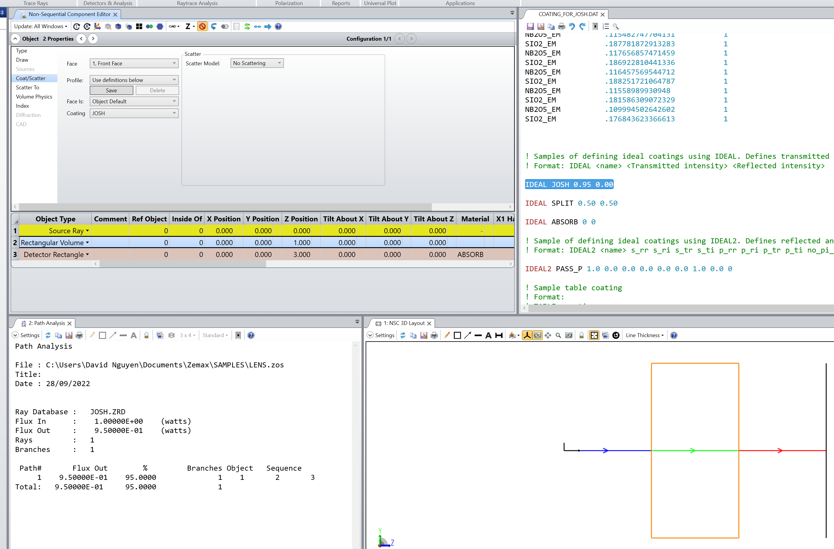
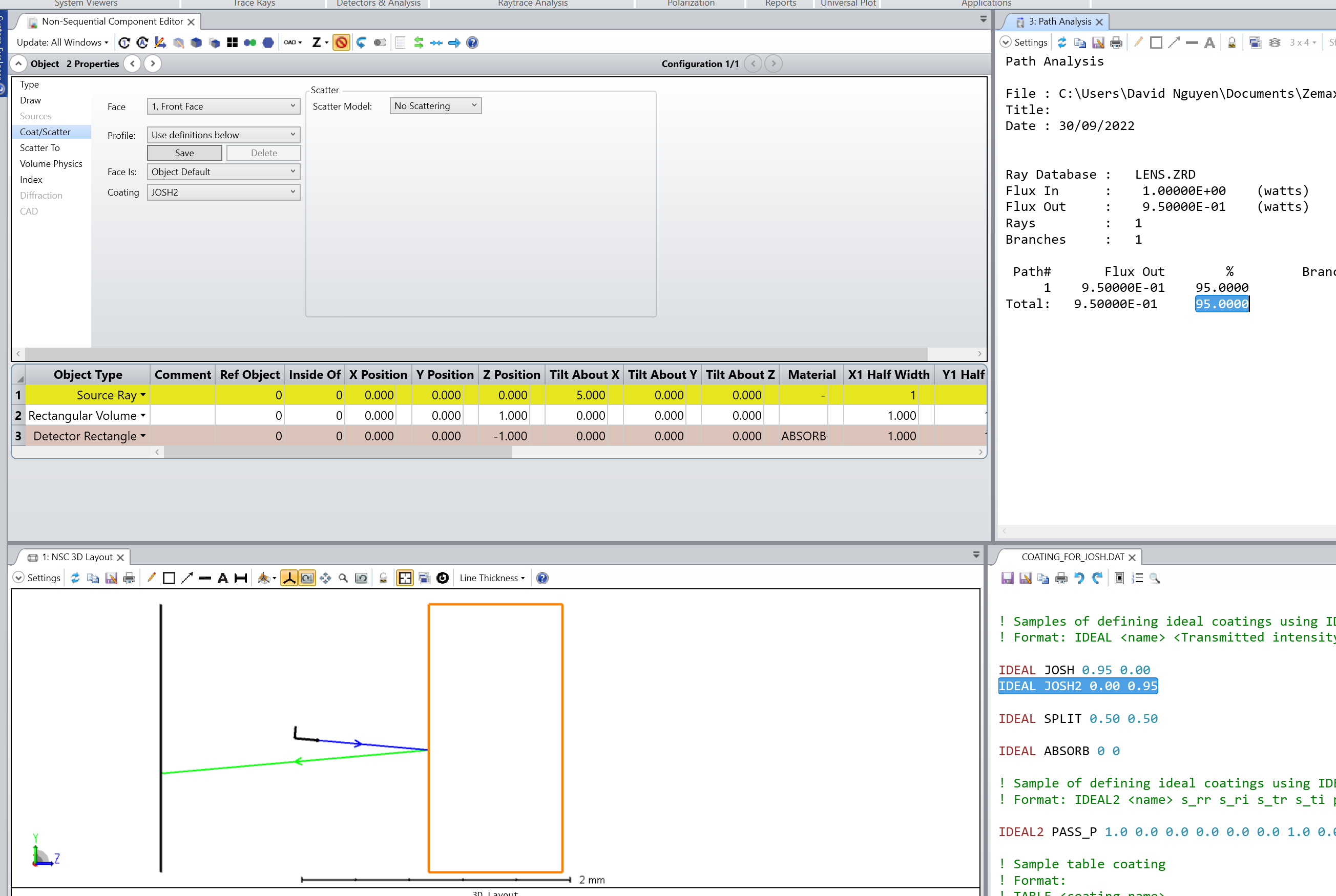
What I’m noticing is that if I add up the number of rays in the path analysis rows, they equal to the number of rays in the ray trace / and in the layout. However, if I add up the powers in the rows, there is a total loss of about 1.8%. I currently do not have any coatings set on the various components (struggling to get that to work for some unknown reason or the other). Just mirror/reflector and absorbers.

Is there an atmospheric loss built into Zemax due to the air the light passes through? I tried setting the air pressure to zero in the System Explorer/Environment to try and simulate a vacuum, and it didn’t change anything. And, if there are air losses, I’d like to control them or set them to zero and calculate the losses numerically. 

Thanks!

icon

Best answer by David.Nguyen 24 September 2022, 12:33

View original

9 replies

Userlevel 2
Badge

Maybe it’s the default MIRROR properties that have some loss or ray splitting? 

Userlevel 2
Badge

Actually, I’m using any default MIRROR properties. It’s just “reflective” and “absorbing” with no coatings. Still some power loss..

Userlevel 7
Badge +2

Hi Josh,


This should answer your question. MIRROR is actually considered as aluminum in OpticStudio, and doesn’t have a reflectivity of 1.0. In air, I don’t think OpticStudio considers any atmospheric losses. If you want to achieve a reflectivity of 1.0, you could consider using an IDEAL coating where you can specify the amount of reflection and transmission you desire.

Hope this helps, and take care,


David

Userlevel 2
Badge

Thanks David,

I mistyped above and I am actually NOT using any of the MIRROR properties. Just pure reflective and absorbing. Still wondering where the missing power has gone. 

I’ve tried to use the Ideal coatings a bit and something is not working right, as the flux on the receiver doesn’t change. I need 95% reflective and 5% absorbing. No transmittance.

Thanks!

Josh

Userlevel 7
Badge +2

Hi Josh,


Not sure why it doesn’t work for you. Here is a simple example I made to demonstrate the IDEAL coating:

I use a Source Ray with a single 1 Watt ray going through a Rectangular Volume. On the Face 1 of the Rectangular Volume, I put an IDEAL coating that I called JOSH (sorry for the not so original name...). This coating is defined in the coating file as:

IDEAL JOSH 0.95 0.00

This means 0.95 percent is transmitted and 0.00 percent is reflected. The remaining 5.00 percent are assumed to be absorbed.

As you can see, the Path Analysis gives the correct transmission. The 3D Layout and Ray Tracing was done with ray splitting enabled (so if the ray were to reflect we would see it, it is just not happening).

The file is attached to my reply.

Let me know if this helps.

Take care,


David

Userlevel 2
Badge

Thanks Dave, 

it looks like you have the coating set for transmitting 95%. How do I set for reflecting 95% and absorbing 5%? 

I used the below, based on the documentation:

IDEAL Heliostat_ref 0 0.95

If these are not correct, then something in my process of using the coatings needs work. 

Thanks,

Josh

Userlevel 7
Badge +2

Hi Josh,


You are absolutely correct. Here is the sample example modified for 95 percent reflection:

Don’t forget to enable Split NSC Rays to visualize the reflected ray.

Hope this helps, take care,


David

Userlevel 2
Badge

@David.Nguyen

Thanks again for the input. Finally got this sorted out.

The reason my IDEAL coating with 95% reflection/5% absorption didn’t seem to work is because a surface (in my case, the main reflecting face of a “Rectangular Volume” object) set to “Reflective” with Coating = “None” apparently includes as default around a 6% absorption loss / 94% reflectivity, as you noted above. And I did indeed have the material set to “MIRROR” in the Component Editor.

What I was seeing is that using the excellent Path Analysis feature, my test surface with 95% reflective coating actually had slightly higher Flux Out and % than with the coating set to “None”. However, a test coating of 50% reflectivity and 50% absorption cut the Flux Out nearly in half. When I created a new IDEAL coating with “0 1”, i.e. 100% reflectivity, as you mentioned then the Flux Out for the test surface was the highest, and the Total Flux for the whole system finally equaled the Flux In, and all fluxes summed to 100%! This solves the original question of where the missing flux went during the Path Analysis and why I wasn't seeing the 95% reflectivity coating have any meaningful effect.

Just curious, is this default loss/reflectivity for MIRROR with no coating in the documentation somewhere?

Thanks again!


Userlevel 7
Badge +2

Hi Josh,


You’ll find that information in the Help File under The Setup Tab > Editors Group (Setup Tab) > Lens Data Editor > Data Columns > Material, here is the relevant section:

If a surface or object has the material type MIRROR, and no coating is specified, then the surface is assumed to be coated with a thick layer of aluminum, with an index of refraction 0.7 - 7.0i. The aluminum layer is assumed to be thick enough that no light propagates past the layer. This means that an uncoated mirror surface has a reflectivity of less than 1, though the exact value will depend on the polarization of the rays.


I hope this answers your quesiton.

Take care,


David

Reply