
Imaging an Aspheric doublet using the operand REAY/X


Forum|alt.badge.img

Hello all,

I hope you are all well in the Corona epoch.

This is my first post. 

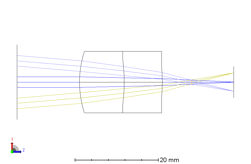
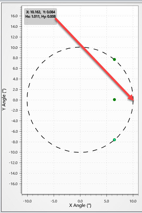
Let's say I am trying to imaging a sensor of 4.8*6.4 mm with Aspheric doublet (FOV 15.2, EFFL 30).

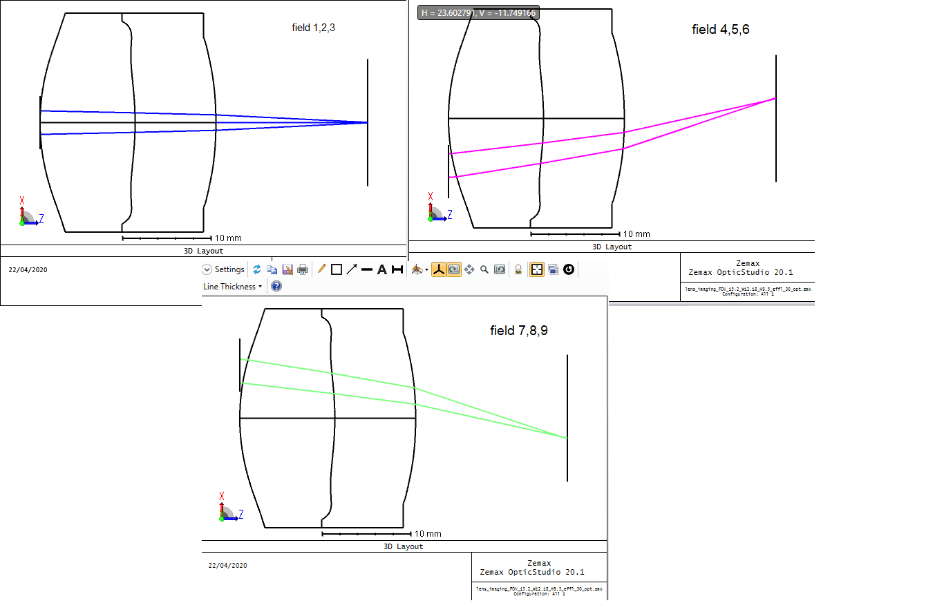
The total Aperture stop is 18*6 mm but for each group of fields(up,center,down) we are intrested in much smaller aperture of 6*6mm(displaced -6,0,6 mm respectively-see attached image). Rays outside ot this smaller aperture don't propagate further into the optical system.

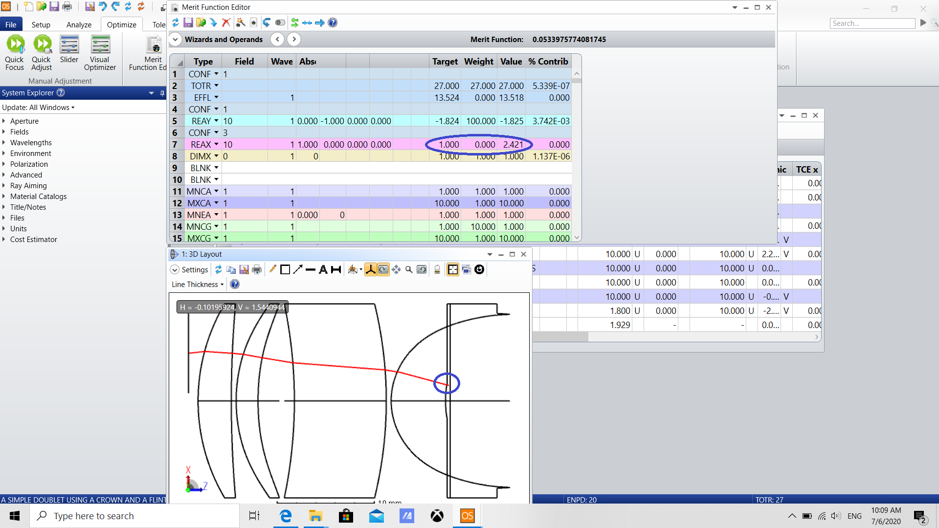
1. I am trying to use the REAY/X operands for this approch by enforing the above rays to arrived to specific smaller aperture. Am i doing it right?

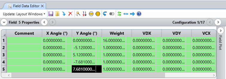
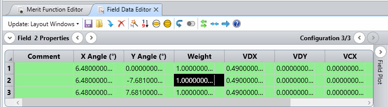
2.  Is there a way to use the multi configurations editor, to displace the apreture stop for each group of fields? I try to do it, but when using the 3d viewer, when choosing all configurations, it seem like it can't be done.

Attached below the zemax files before and after opitmization and the merit function file.

Many thanks,

Nadav


differentfields.png
Did this topic help you find an answer to your question?

14 replies

David
Luminary
Forum|alt.badge.img+4
  • Luminary
  • 336 replies
  • April 23, 2020

Hi Nadav,

Perhaps you realy want the stop between the lens and the sensor? In that case, OpticStudio will fill the stop with rays. Of course, the design itself needs a real stop. I add a modified file as a ZAR.

Kind regards,

David


Forum|alt.badge.img+2

Hi Nadav!

Here is the alternative solution where the stop is at the front.

In the multi-configuration editor, I used the following operands:

  • APDY to decenter the aperture
  • FVDY to decenter the pupil
  • XFIE to define the different fields

To have a correct view of the system, I changed the Global Coordinate Reference Surface to 5 (the image plane) in the System Explorer > Aperture.

I have attached the result.

I didn't do any modifications to the merit function, but let us know if you need any help on this.

Thank you!

Sandrine


Forum|alt.badge.img
  • Author
  • Fully Spectral
  • 89 replies
  • April 23, 2020

HI.


Thanks alot for the help and the quick repleys, David and Sandrine!

1. David, I tried your solution with different size and distance of forward stop but i can't get the requiered apreture for each field.

2. Sandrine, it's look great! I will try it.


Best regards,

Nadav


Forum|alt.badge.img
  • Author
  • Fully Spectral
  • 89 replies
  • April 24, 2020

hello, 

Is there a way to give more weight only for the field 0,0?


Best Regards,

Nadav


Forum|alt.badge.img+2

Hello again,

Have you tried the field weight operand in the multi-configuration editor?

Sandrine


Forum|alt.badge.img
  • Author
  • Fully Spectral
  • 89 replies
  • April 27, 2020

Hello Sandrine,


No. FLWT looks to do the work again!

Thank you!


Best regards, 

Nadav


Forum|alt.badge.img
  • Author
  • Fully Spectral
  • 89 replies
  • June 28, 2020

Hello again,

I am trying to design a collimator for monochromate(570nm) microdisplay 3.648*3.072 mm.

The spec of the system are:

-20 degree FOV diagonal(~13.55 mm focal length)

-small TOTR 

-differenet apperture location for each field

I used the APDX and FVDY operands, and the REAX/Y operands to specify the focal length.

Attached bellow the files before and after optimization(hammer+global).

1. Do i need to use only 1 operand of reax/y or several?

2. I tried to change the order of parameters in the optimization(i.e. first radii,2 conic section, asphere terms of 2 surfaces-then making the thickness and the other conic/asphere terms also variables etc...)   but still got some abberation at the edges of the image.

Do you have any tips for improving the design?

Thank you very much,

Nadav


Forum|alt.badge.img+2

Hi Nadav

Thank you for sharing your file.

- There are a lot of configurations in this file and I am not sure all are actually necessary. For example, Configs 1 to 5 are using the same STOP and each config defines a different field. I would make this into one config.

And I have done the same for all the other configs and ended up with 5 configurations.

For config 1, we have 5 fields but for configs 2-5, we only have 3 fields (so I ended up copying field 1 into field 4 and field 5).

But actually I think it shows an issue. It means that we don't use the same sampling for the center and the edge. So if you have issue at the edge, I would recommend setting 5 fields for all configs.

- The merit function should contain your own operands at the top and then the Default Merit Function. It will avoid overwritting your lines when you update it.

Each operand is given in a specific configuration. To specify the focal length, I think you only need to do it on the new config1, which is the on-axis configuration.

- Regarding the optimization, I have seen that you used the Rectangular Array as some rays are vignetted. The default of this method is that it sends a lot of rays. So I would recommend using the Gaussian Quadrature as a 1st start and then move to the RA.

So once you have modified the sampling of the fields, try optimizing. I haven't corrected the merit function in the file that I have attached, it needs to be rebuild. Then as you said you can add complexity, but if the sampling is the same I think that would help.

Also when you are optimizing, check what is driving your merit function. That will give you an indication to see if the merit function is properly built.


I didn't do any optimization.

Let us know if that helps.


Sandrine


Forum|alt.badge.img
  • Author
  • Fully Spectral
  • 89 replies
  • June 29, 2020

Hello Sandrine,

It's seems to work! thanks!

just to make sure:

1. You write: 'So once you have modified the sampling of the fields'.

I am not sure I understand to what operand you are referring.

2. Can i use the Gaussian Quadrature even if i have rectengular apreterue stops?

Again, many thanks for your quick help and the detailed reply,

Nadav


Forum|alt.badge.img+2

Hello Nadav

Good! I'm happy that my suggestions help.

  1. By the sampling of the fields, I mean the fields defined in the Field Data Editor. This is the way the field is sampled. The merit function automatically creates operands for the different fields.
  2. Well you can use Gaussian Quadrature but it will ignore your rectangular aperture. However (and because it is quick as it sends less rays), I would give it a try. It may give a nice starting point for your optimization. Then I would switch to Rectangular Array.
    No guarantee on this, but I think it is worth a try.

Sandrine


Forum|alt.badge.img
  • Author
  • Fully Spectral
  • 89 replies
  • July 6, 2020

Hello Sandrine,

Thanks for the suggestions. It seems to work much better now.

Some further questions:

1. If I used the Gaussian Quadrature and got good enough results( mtf, etc.), is there any need to optimize again using rectangular aperture to get more accurate results?

2. After optimization I used the REAX operand for  field 3, configuration 3 to make some sanity check, i got some strange result: The ray location according to the 3d viewer and the calculation supposed to be at X=1.52~ while at the merit function i have X = 2.42 (Attached bellow).

What is wrong?

Best,

Nadav


Many thanks again,

Nadav


image.png

Forum|alt.badge.img+2

Hello Nadav

I'm glad to read your email.

1. Have you checked you results with the analysis or with the merit function operands? I would just make sure that the performance is good enough when calculated with the rectangular aperture.

2. The REAX operand on line 7 of the merit function is calculated for configuration 3 for the chief ray of the field (HX=1,HY=0). If I look at the field data editor, this is a X = 10.049 degree, due to the circular normalization:

If you trace that ray using Analyze > Rays & Spots > Single Ray Trace, you will see that this ray is vignetted.

If you'd like to trace this ray, you will need to add a new field in the field data editor (X angle = 10.049, Y angle=0). This ray is not traced.

So I think it raises a good question about your field definition. Is your field normalization correct? Currently it is radial. If that is correct, a field should be added in the field data editor as well as in the merit function.

Sandrine


Forum|alt.badge.img
  • Author
  • Fully Spectral
  • 89 replies
  • July 6, 2020

Hi,

1. I  checked the results with the analysis tab (mtf).

2. I dont need to trace the field X= 10.049 but the X = 6.48. Y= 0  field. it seems okay now when using Hx= .645 , Hy = 0 

I think the cirucular normalization + configurations confuse me a little bit.

Thanks again,

Nadav


Forum|alt.badge.img+2

Ok! Good. Thank you.


Reply


Cookie policy

We use cookies to enhance and personalize your experience. If you accept you agree to our full cookie policy. Learn more about our cookies.

 
Cookie settings