Issue ray tracing after mirror reflection - curvature of radius fails
I am running into an issue placing lenses following a mirrored surface.
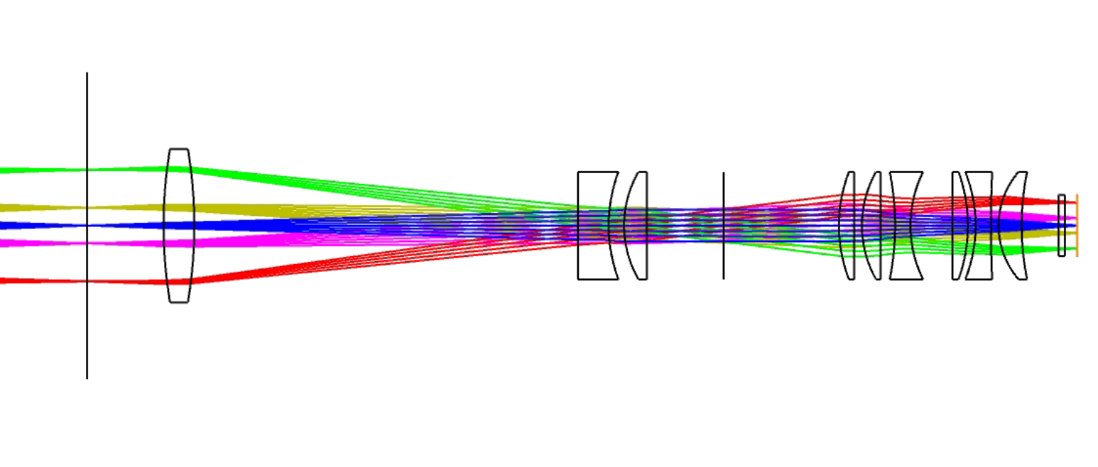
Here is my design in sequential mode:
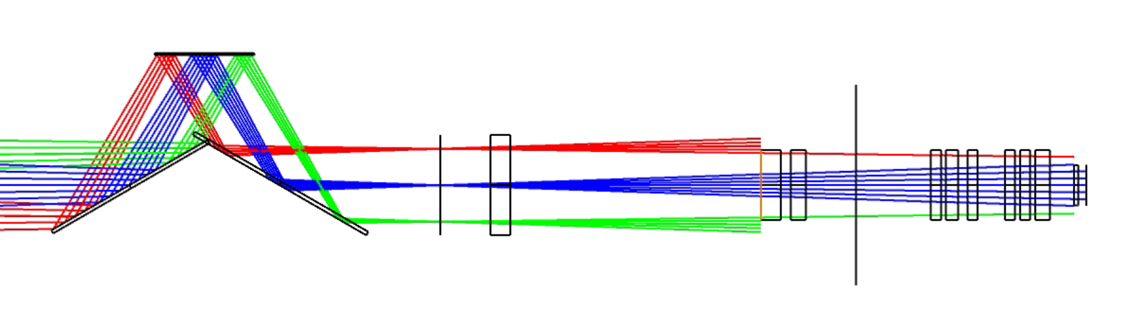
Then I add K-mirror before the lens assembly in non-sequential mode:
After the mirrors are added changing the curvature of radius of the lens assembly fails. The light is not reflected through the lenses and Zemax draws the lens as large circles. Any clue as to what is causing the issue?
Page 1 / 1
What is your Ray Aiming set to? Try Paraxial, cache on.
Since there are 3 mirrors, you have odd parity. Are you changing your radii to the opposite sign?
Run the Setup > System Check (the stop light button) and see if there are any errors.
Also, for these surfaces, open the Lens Data Editor Surface property and check the box for Type > Surface Cannot Be Hyperhemipheric.
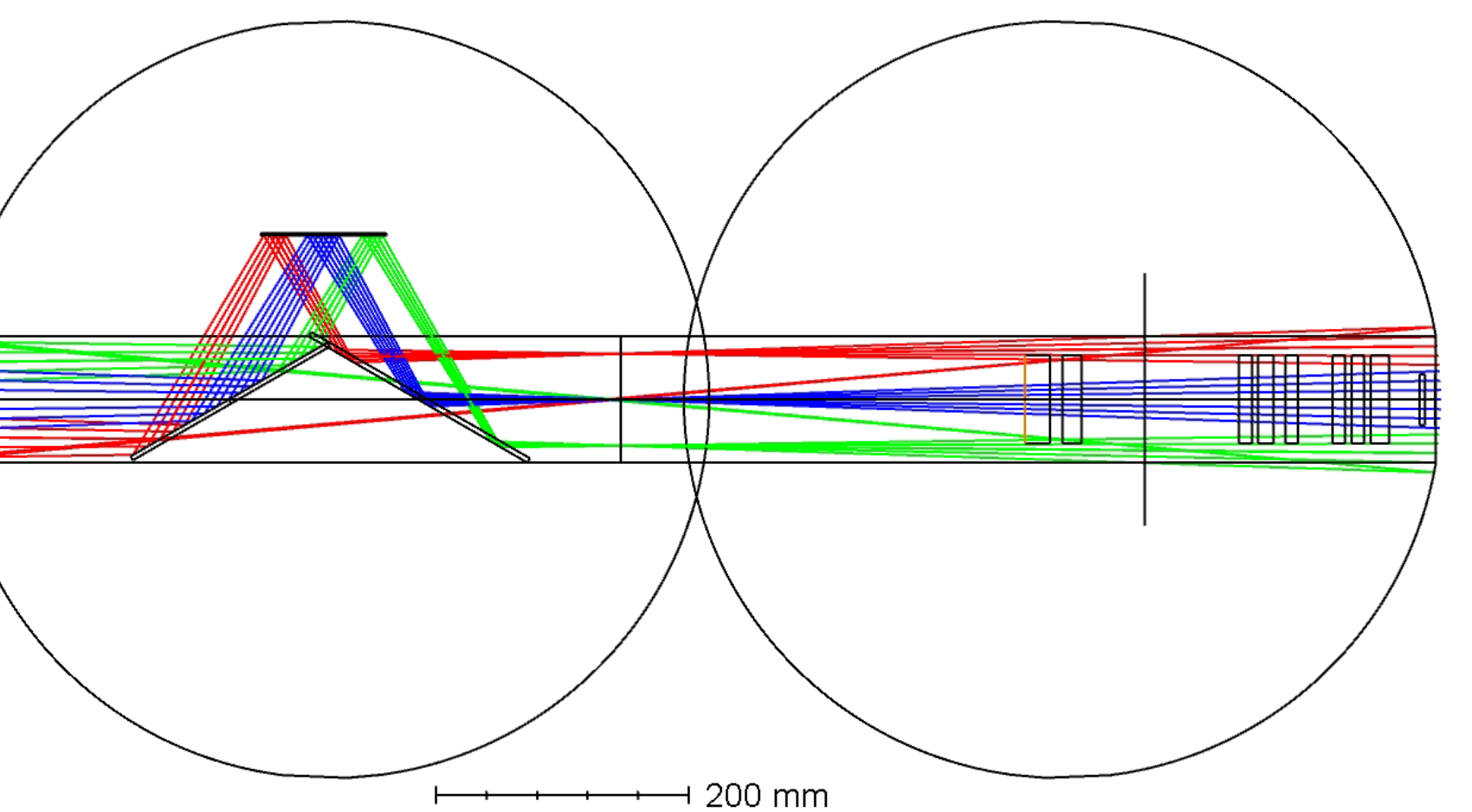
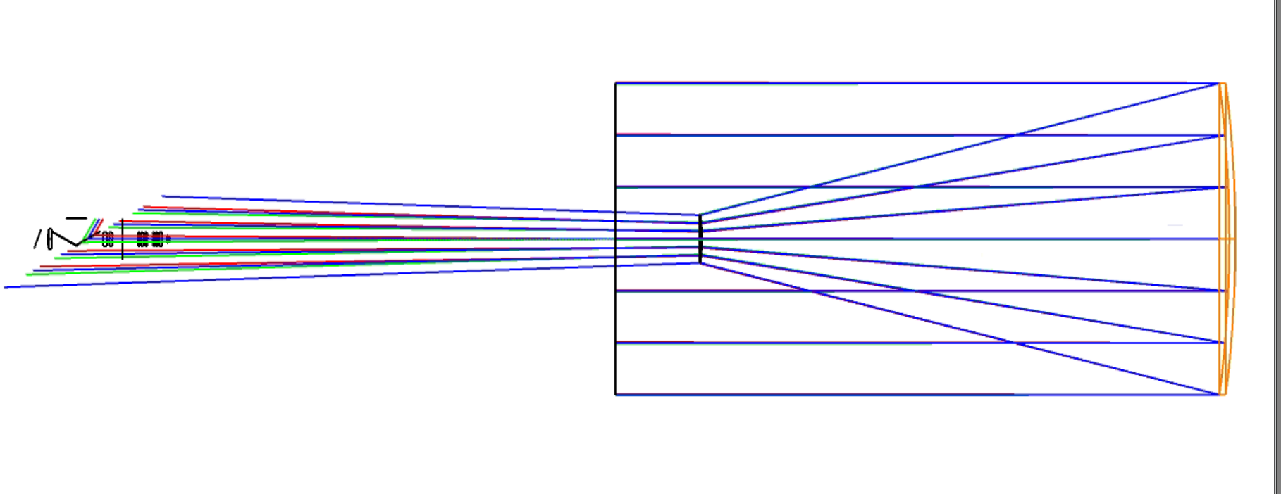
Thank you for your answer! Changing the sign of the curvature does not fix my issue. Checking the lenses “cannot be hyperhemipheric” does help remove the giant circles, but as you can see in the image the light still is not tracing correctly.
I ran the system check and got the error: “Angle of incidence for chief ray exceeds 90 degrees” on the 3rd mirror surface and all the surfaces following. I never used this feature before so thank you for sharing. I can see though that the angle of incidence is not greater than 90 so I am still wondering what causes this problem.
Hey Ramona,
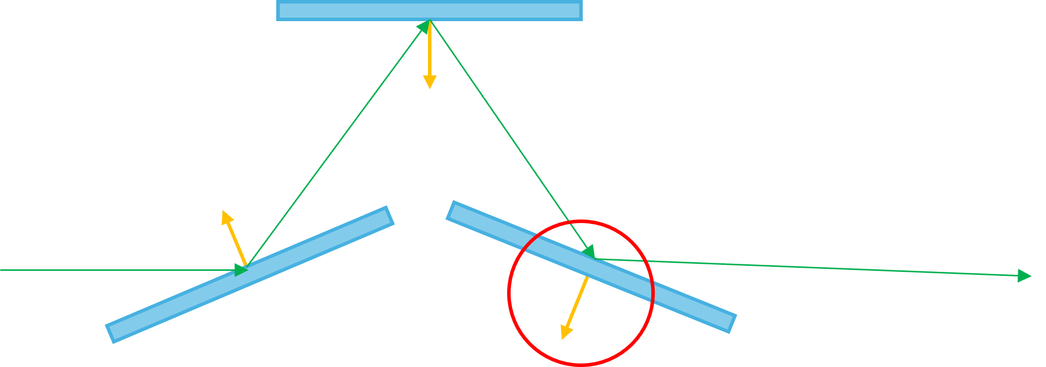
Since rays extend to both positive and negative infinity, you’ll have 2 angles the ray makes with the mirror:
θ
180° - θ
The reported angle depends on the mirror’s local axis. OpticStudio always expects the dot product (angle of incidence) the ray and the local axis to be less than 90°. Although you don’t show the local axis, I believe your third mirror has a local axis which is pointing down and to the left:
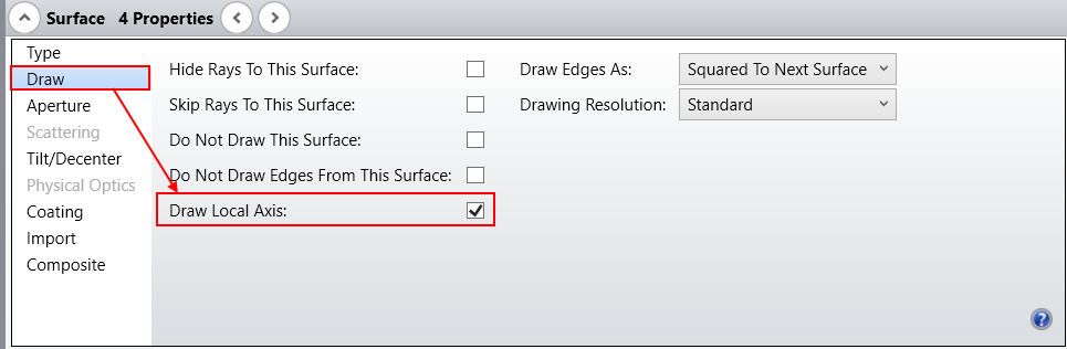
You can show the local axis by clicking the Draw Local Axis box in the Lens Data Editor’s Properties section:
If this is the case, then you should be able to simply rotate your third mirror by 180° so the local axis is pointing up and to the right.
If this doesn’t work, can you please share your file. That will help with the debugging process.
Hey Ramona,
Since rays extend to both positive and negative infinity, you’ll have 2 angles the ray makes with the mirror:
θ
180° - θ
The reported angle depends on the mirror’s local axis. OpticStudio always expects the dot product (angle of incidence) the ray and the local axis to be less than 90°. Although you don’t show the local axis, I believe your third mirror has a local axis which is pointing down and to the left:
You can show the local axis by clicking the Draw Local Axis box in the Lens Data Editor’s Properties section:
If this is the case, then you should be able to simply rotate your third mirror by 180° so the local axis is pointing up and to the right.
If this doesn’t work, can you please share your file. That will help with the debugging process.
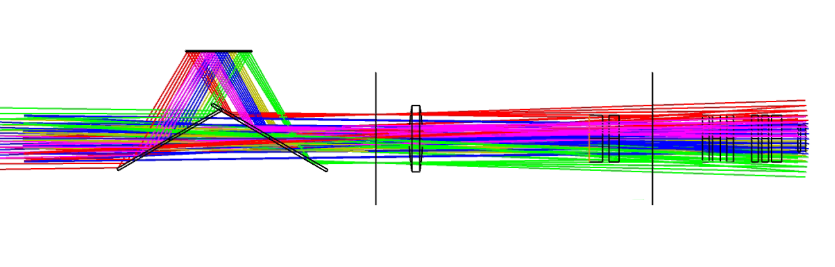
Thank you for your helpful response! The local axis of the third mirror was actually already pointing up. When I rotate the mirrors by 180 the angle of incidence errors go away, but then the system only traces virtual rays in the wrong direction.
I will share my file here:
Hi Ramona,
You have virtual rays because the thicknesses are all positive. If you have an odd number of mirrors (in your file, you have 5 mirrors), then all the thicknesses need to be negative (and the radius needs to have the opposite sign as what you would normally use).
Hi Ramona,
You have virtual rays because the thicknesses are all positive. If you have an odd number of mirrors (in your file, you have 5 mirrors), then all the thicknesses need to be negative (and the radius needs to have the opposite sign as what you would normally use).
I appreciate you looking at my file. Negative thickness makes no sense to me because if I do that, the lens assembly is on the wrong side of the telescope and the order is all wrong. The thicknesses are chosen because that is where I need them placed, if its negative they are in the wrong spot.