What is the method of setting up reverse radiance feature on premium? with a source placed at the detector at the focal plane or else where.

Page 1 / 1
Hi Nicholas,
For ReverseRadiance, there is not a requirement that the detector be placed at the focal plane. Have you found the Help System file on this tool? It is located here: The Analyze Tab (non-sequential ui mode) > Applications Group (the analyze tab, non-sequential ui mode) > ReverseRadiance. It provides a full description of the setup considerations that are required. I'm pasting it below for your reference!
Best,
Allie
The ReverseRadiance™ Method
There is an alternative method that works very well for some systems. The method involves tracing rays backwards, from the detector to the source. The idea is to trace only those rays that hit a given pixel on the detector. Since it is not know which rays leaving the source hit the detector, the ray is instead traced from the detector towards the source, and the amount of flux is then assigned according to the flux of the source at the position and traveling in that ray direction. There are several complications with this method:
- The ray needs to trace from the detector in a direction that will likely eventually hit the source
- The ray tracing routine must be able to detect that the ray has 'hit' the source
- The radiance (or illuminance) of the source must be known given the ray wavelength, position, and angle
- There must be enough sample rays to account for all likely paths to the source from a given detector
The ReverseRadiance™ feature supports this method of computation. There are several steps that must be carefully done for this the analysis to get accurate results, as described below.
Defining the source object
The Source must a Source File as described in “Source File” . In addition, the source file must have been generated using the Radiant Source Model™ ray file generation feature described in “Generate Radiant Source Model Rays” . This step is important, because only the Radiant Source Model™ files contain the actual measured radiant or luminous intensity as a function of wavelength, position, and angle; and this data is required for proper integration of the flux incident upon the detector. Without this data, the ReverseRadiance™ method will compute zero flux on the detector.
Defining the boundary object
Because the source object is a list of rays, it needs a separate object to define the physical extent of the source. This object can be any shape that closely follows the actual physical shape of the source. It may be a sphere, cylinder, rectangular cube, or any other shape supported. It is not required that this object have any physical propertes - its purpose is only to allow the raytrace algorithm to detect when the reverse ray has reached the vicinty of the source. Once the ray is close enough to the source to intersect the boundary object, the ray trace is terminated and the flux is computed as described below.
It is usually a good idea to set the 'Rays Ignore Object' to 'On Launch' for the boundary object, so that forward tracing rays do not interact with the boundary object. This setting is on the 'Type' tab as described in “Type tab”.
Defining the target object
When the reverse rays are launched from the detector, it vastly increases the efficiency and accuracy of the analysis if the rays trace in a direction that ultimately will intersect the boundary object, and by extension, the source itself. The target object is a special type of NSC object called the ReverseRadiance™ Target, as described in “ReverseRadiance Target”.
The target object supports these parameters:
- Shape: Use 0 for a rectangular target, 1 for an elliptical target.
- X/Y Half Width: The size in lens units of the entire target.
- #X/Y (or Radial/Angular) Pixels: This divides the entire target into smaller pixels.
The pixels on the target have a special purpose. One ray will be traced from each detector pixel to the center of each target pixel. This is how the sampling and accuracy of the integration is controlled. More pixels on the target object means a slower computation, but more accurate results. Even with moderately high sampling, far fewer rays are usually needed for accurate results than is the case with forward ray tracing. The number of pixels on the target can be increased until the results converge.
Defining the detector object
Within the NSC Editor, add a ReverseRadiance™ Detector object as defined in “ReverseRadiance Detector”. This object defines the position and size of the detector, as well as the number of pixels for which the reverse computation will be performed.
The detector object has several parameters used to define the detector properties:
- Shape: Use 0 for a rectangular detector, 1 for an elliptical detector.
- X/Y Half Width: The size in lens units of the entire detector.
- #X/Y (or Radial/Angular) Pixels: This divides the entire detector into smaller pixels.
- Source Object: This is the object number of the Source File described above.
- Target Object: This is the object number of the ReverseRadiance™ target described above.
- Boundary Object: This is the object number of the boundary object described above.
- Reverse Ray Color: The pen color to use when drawing rays from this detector. If zero, the default color will be chosen.
Reverse radiance would be a very useful tool except that it is limited to using Radiant Source Models. Unfortunately the Radiant Source Model file format is a proprietry file format and these files can only be generated from measurements of actual sources. Although in theory it would be possible to generate a Radiant Source file from a simulated source because it is a closed file format you can't do it yourself and Radiant Imaging don't have any software that can generate this file format from anything other than measurements.
Zemax must have put in quite a bit of development effort in to Reverse Radiance but because of this one limitation it is very seldom used, (judging by the number of questions on the forum other than how do you use it). To make it of more general use Zemax needs to allow other sources to be used with it. It needs just a bit more development from Zemax to allow it to work with elliptical and rectangular uniform area Lambertian emitters and uniform volume emitters such as ellipsoids, cylinders and boxes to make it a really useful tool.
Andrew
Hello Andrew,
Thanks for your comment and feedback here!
The idea of updating the Reverse Radiance tool to work with built-in geometric sources has been brought up before by other users too. Thank you for bringing this to our attention again. We already have a feature request on this in our internal system, so I have gone ahead and voted for it on your behalf.
Please keep in mind that feature requests are weighed based on impact, difficulty to implement, and the number of users who request it. A request is not a guarantee that the feature will be added to a future release. However, these feature requests are very important to us and shape the future of OpticStudio, so we appreciate your input regarding desired functionality.
Thank you,
Csilla
Hi all,
I have attached a file that uses the Reverse Radiance tool. I thought it would give a better idea of how it works (and also its current limitation).
The zar file does not contain the RSMX file (it will need to be downloaded from the libraries):

I answered No to that question. This is because forum attachments are limited in size.
So here is the lens data editor:

It contains a source file, a Reverse Radiance Target and a ReverseRadiance Detector.

Then the Reverse Radiance tool needs the following settings:
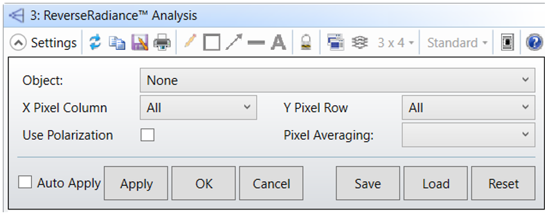
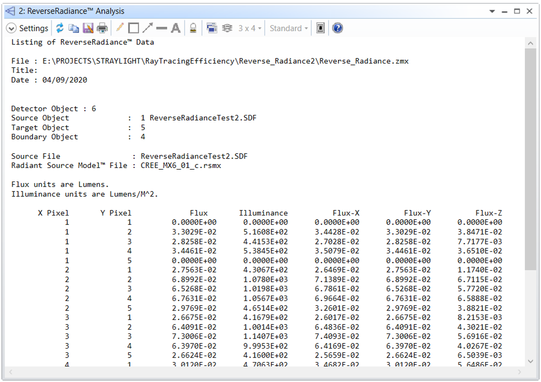
The result is a text report.
There is a YouTube video (that dates a bit) that explains this feature: https://www.youtube.com/watch?v=bQgu7oUF1-0
Sandrine
Our application could benefit greatly from reverse radiance, but we need a Radiant Source Model that is a gaussian spatially and a lambertian in angle with configurable parameters. I dont see that in the 750 models available. Any way to get something like that added?
Hi Alon,
Can you let me know how you searched through all the models in the Radiant catalog? It seems to me that this type of setup is not very unique and should be available. Are you looking at a particular vendor?
To obtain this type of model, I would recommend going directly to the vendor or to Radiant Vision Systems to request an RSMX file for use in OpticStudio. If they can provide a RS7, RS8, or RS9 file, we are also able to convert that for you.
Best,
Allie
Hi all,
has there been any progress on improving the Reverse Radiance feature to be used with user defined sources? This would also be very helpful for me.
Thanks,
Josh
Hi zemax team
I can also only support this request. It would be great if you could allow reverse raytracing for all user generated light sources. Especially sources created from saved ray tracing results.
Thanks!
Enter your E-mail address. We'll send you an e-mail with instructions to reset your password.
Need more help?
To Chinese users:
Do not provide any information or data that is restricted by applicable law, including by the People’s Republic of China’s Cybersecurity and Data Security Laws ( e.g., Important Data, National Core Data, etc.).
不要提供任何受适用法律,包括中华人民共和国的网络安全和数据安全法限制的信息或数据(如重要数据、国家核心数据等)。