Solved

How to use a Non-sequential Component CAD file mirror in Sequential mode (="mixed mode") ?

  • December 22, 2022
  • 5 replies
  • 355 views

Forum|alt.badge.img

Hi,

Before explaining my issue, I should let you know that I have already checked this article on Zemax website : https://support.zemax.com/hc/en-us/articles/1500005577002-How-to-model-a-mixed-sequential-non-sequential-system

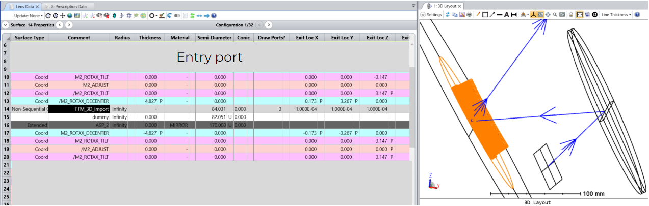
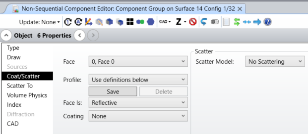
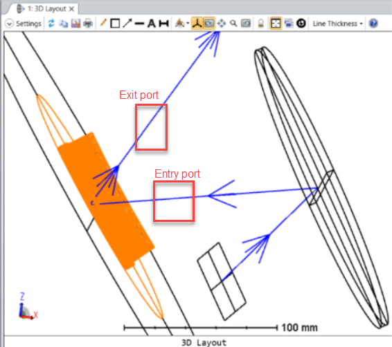
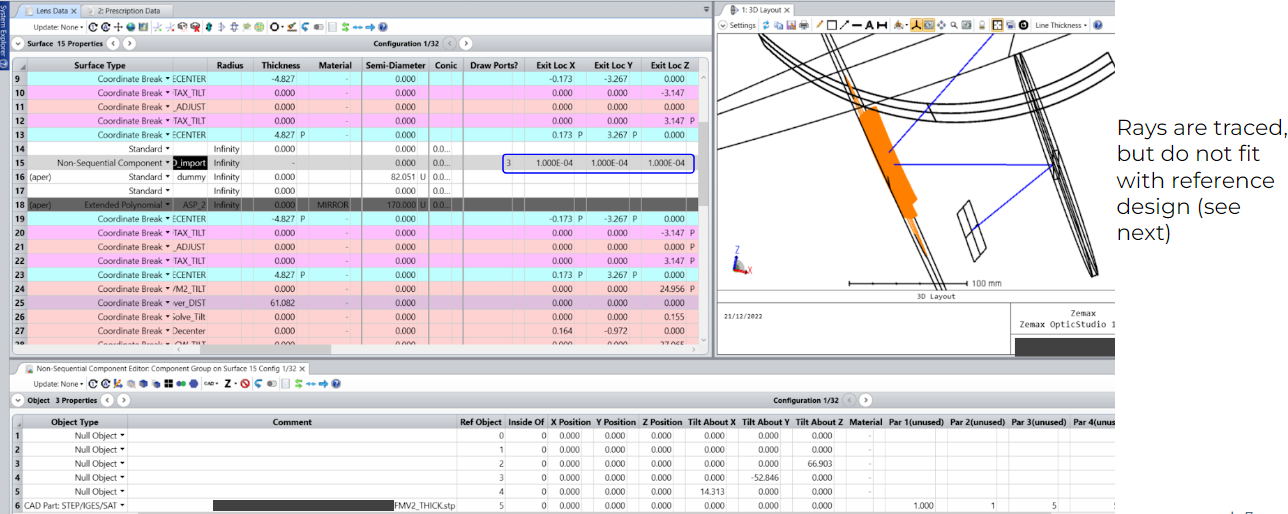
Here, my goal is to study the use of a Freeform mirror (FFM) as a stp. file, knowing its polynomial equation. To get it, I am doing a 3D export of a known HUD optical design. Then, the FFM defined as an extended polynomial is ignored, and the non-sequential FFM is imported. The dummy surface that followed should be the exit port.

Please, find below few pictures of the situation :


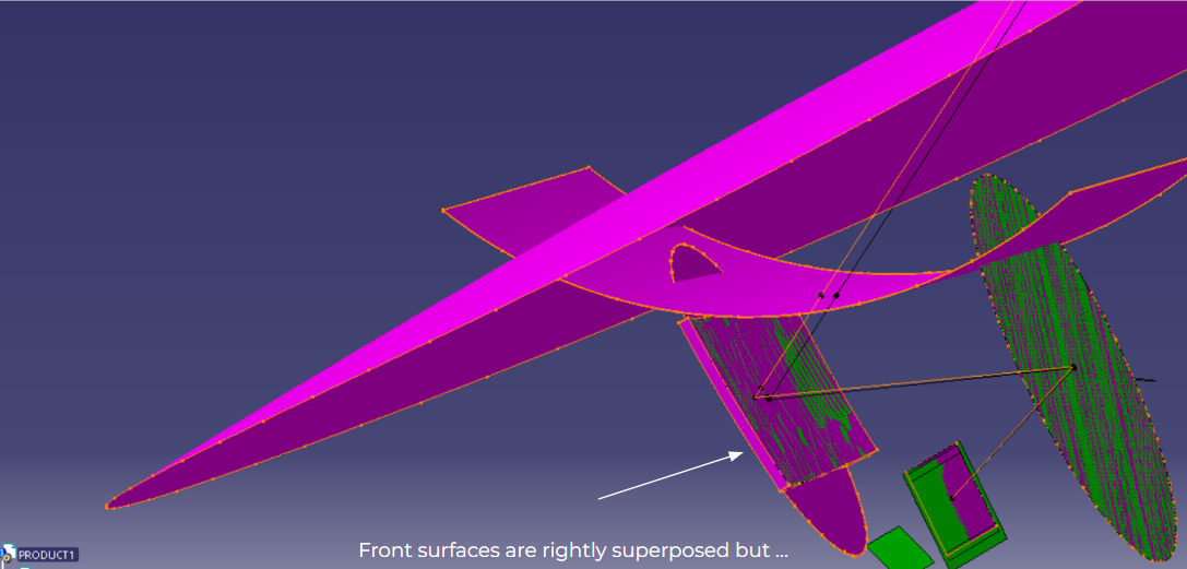
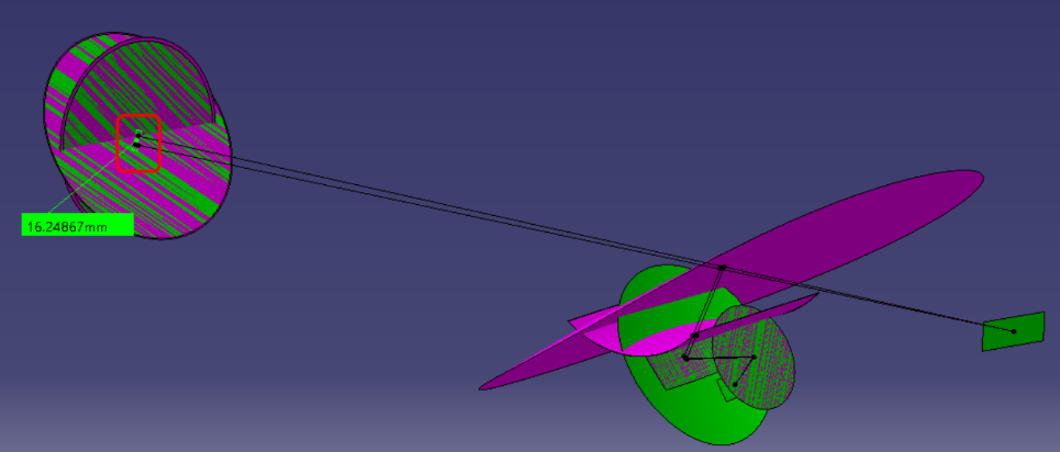
The nominal design is in green, and the new one with the FFM as a CAD file is in purple.

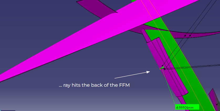
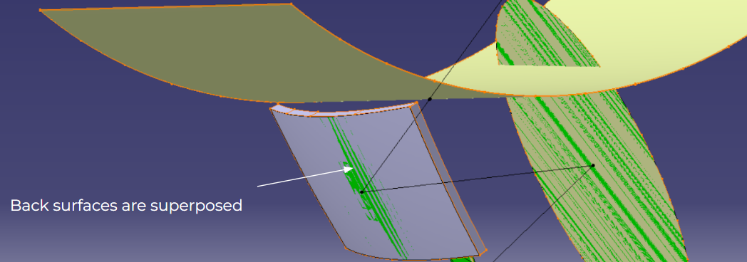
As you can see, front surface of CAD FFM is well superposed with the green one, but the ray is hitting the back of the imported FFM, leading to a shift in the virtual image plan at the end.

Since the thickness of the FFM is 5mm, we can measure almost 5mm between the reflexion point on the FFM of the nominal design and the reflexion point of the CAD FFM.

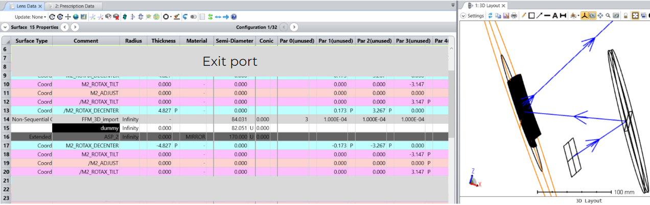
In Zemax, I have tried to shift this CAD FFM from 5mm in order to compensate, but then an error occurs : 


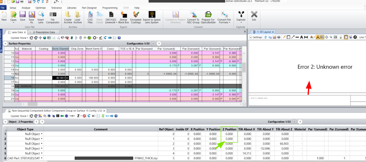
(Nominal design is in green)

The back CAD Freeform (where the reflexion occurs previously) is now in the reflexion plan of the nominal design, but the ray cannot be traced in Zemax…

Could I have your help on this topic ?

Best regards,

Nicolas Letort 

Best answer by Sandrine Auriol

Thank you. The properties look correct. For the ports I would expect something like this:


View original
Did this topic help you find an answer to your question?

5 replies

Forum|alt.badge.img+2

Hi @Nicolas.Letort !

Sorry if this is a simple remark but have you ticked “Reverse Rays”? Can you share your design or send it to the support so we can have a look?


Forum|alt.badge.img

Hi Sandrine,

Yes indeed I have ticked this “reverse rays” option. My guess is that entry/exit ports are not well defined. Is it possible to manage them in a way to have the reflexion on the front surface of the CAD Freeform Mirror ?

To overcome this issue raised by FFM’s thickness, I have tried with a CAD surface and not a volume but it doesn’t work, as it is mentionned in the documentation of “CAD Part : STEP/IGES/SAT” type.

Best regards,

Nicolas Letort


Forum|alt.badge.img+2

Yes that might be the case. Can you show where your ports are and fletch your rays?


Forum|alt.badge.img

The non sequential component properties are set like this :


Forum|alt.badge.img+2

Thank you. The properties look correct. For the ports I would expect something like this:


Reply


Cookie policy

We use cookies to enhance and personalize your experience. If you accept you agree to our full cookie policy. Learn more about our cookies.

 
Cookie settings