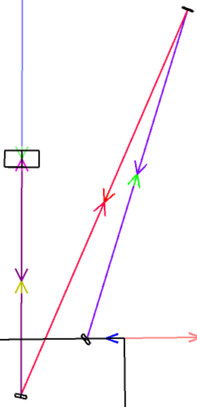
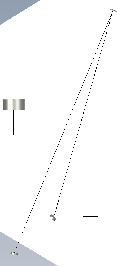
I have an NSC layout in OpticStudio that includes some mirrors and a beam that is modeled as a Source Ray. I see the beam in the layout and I want to export the layout as a Step file. (The layout is it appears in OpticStudio is attached.) When I view the Step file, a segment of the beam is missing. (The layout as it appears in the Step file is also attached.) The segment of the beam that passes through the large optic (light purple in the OS layout) is missing from the Step file and I’m not sure why. I’ve tried changing the source type for the beam, the power of the beam, the coating on the large optic. I even tried removing the optic, but this causes both the light purple and the maroon segments of the beam to be missing in the exported file. Any help would be greatly appreciated.
Page 1 / 1
Just as a follow up, I want to mention that the length of this beam segment is quite long (on the order of 10^5 mm). I’m not sure if there is a limit to how long an exported beam can be? But I tried creating a cylindrical object of the same length as the beam and this object is able to be exported in the Step file. I’m not sure why the beam will not export.
Thanks for your response. To view the STEP files, I am using eDrawings and also OpticStudio (importing the STEP file back to OS).
Thanks for sending that link.I looked over the article and checked to make sure I was using the same settings. I noticed that for me the option to change the number of rays is grayed out, but I’m not sure why. Does this depend on the source type? I’m modeling my beam as a source ray.
Hi Camillem,
In the CAD export control window, the Number Of Rays and Ray Pattern options are greyed out because these options only apply to pure Sequential mode. When you are in NSC mode, the rays included in the CAD export is specified by the # Layout Rays parameter entered for the Source.
I don’t think 1E5 distance is the issue here. Without seeing the file it’s a bit difficult for me to be certain, but I wonder if the range of surfaces you choose to export has an impact on which segment of rays the CAD export will include. Would it be possible for you to add a dummy object in front of the “large optic” and try CAD export again? With a dummy object in front, maybe the light purple ray segment will be included in the CAD export? If you still cannot figure this out, I would recommend to reach to support@zemax.com and include the file, or a dummy version of this file so we can take a look and better understand the issue here?
Best regards,
Hui
Hi Hui Chen,
Thanks for your response. I sent the file to support@zemax.com to see if they might have some insights. Thanks!
Hi Camillem,
Thanks for sending over your files to Zemax Support.
I have taken a look at it and sent you my findings. We can continue the discussion there specifically about your file, and maybe come back here with our general final findings.
Best, Csilla
Hi again,
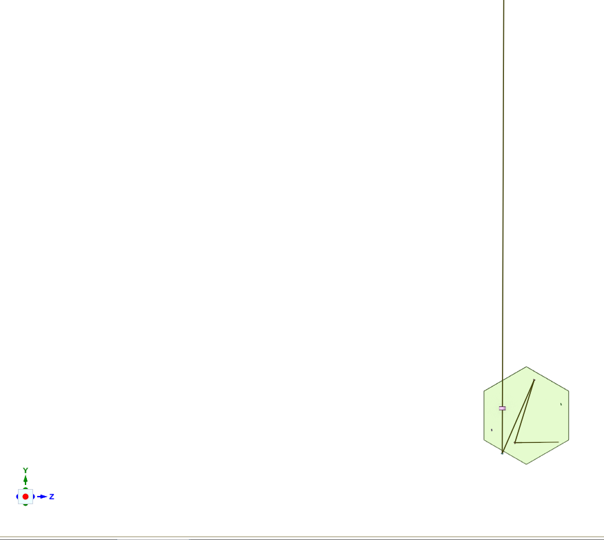
Based on our tests it seems that the problem is with the eDrawings CAD tool specifically. All the segments of the ray are drawn correctly in the STEP file when using SpaceClaim or Autodesk Inventor as a CAD software:
I would suggest to try using another CAD software instead of eDrawings.