How do I do that?


 +2
+2Best answer by Allie
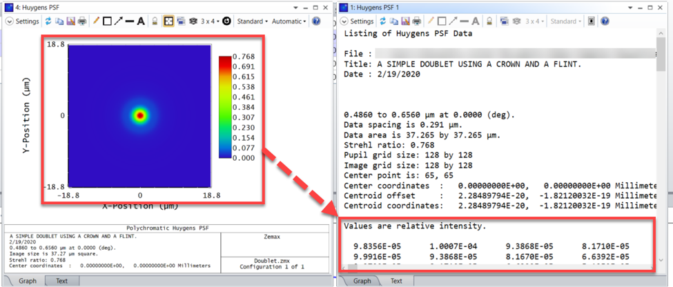
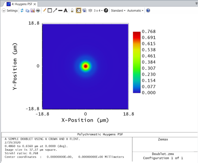
These types of plots (Huygen's PSF, Wavefront Map, Detector Viewer, etc.) are generated with a matrix of data points provided within the "Text" tab of the same analysis window. This matrix data may be pulled into the API using the ZOSAPI.Analysis.Data.IAR_ Interface and made into a figure.
Analysis window data is split into multiple categories within the IAR_ Interface. A matrix of data (shown above) will typically be provided as a DataGrid while a 2 column list of data (such as that given by a Cross Section plot) will be provided by a DataSeries. Sometimes, analysis window results are not pulled into the API, in which case we must pull the results into an external text file. See "Generating a list of output data types for each analysis in the ZOS-API" for more information.
As long as the data is accessible, we can pull it into the API using the corresponding IAR_ Interface property. Below is a Matlab example of this process:
TheSystem = TheApplication.PrimarySystem;
% Open the Huygen's PSF. We will use the default settings for now
huygensPSF = TheSystem.Analyses.New_HuygensPsf();
% Run the analysis with the current settings and pull the results
huygensPSF.ApplyAndWaitForCompletion();
huygensResults = huygensPSF.GetResults();
% The results will be split into multiple data structures
% One structure will house the header information
% Another structure will house the relative intensity values
% Pull the structure with the intensity values
matrixData = huygensResults.DataGrids(1).Values.double;
% OpticStudio has pixel (1,1) in the top left of the matrix
% Matlab places the (1,1) at the bottom so we need to flip the matrix
huygensData = flipud(matrixData);
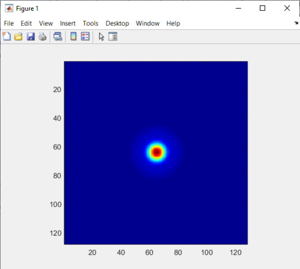
% Use pixel data to create a figure
% The jet colormap will match closely with the False Color plot
imagesc(huygensData)
colormap jet;
axis square;
% Close the Huygen's plot
huygensPSF.Close();
Enter your E-mail address. We'll send you an e-mail with instructions to reset your password.
Do not provide any information or data that is restricted by applicable law, including by the People’s Republic of China’s Cybersecurity and Data Security Laws ( e.g., Important Data, National Core Data, etc.).
不要提供任何受适用法律,包括中华人民共和国的网络安全和数据安全法限制的信息或数据(如重要数据、国家核心数据等)。