Question

Multiple Pressure Enviroments in a Single Configuration

  • February 27, 2025
  • 3 replies
  • 86 views

Anthony

Hello,

I am having an issue with defining multiple pressure environments in a single configuration. I have seen other folks ask a similar question on this topic in the forum before but I seem to have ran into an issue that I can’t seem to resolve. I am using Zemax version 2024 R2.

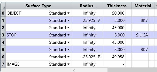
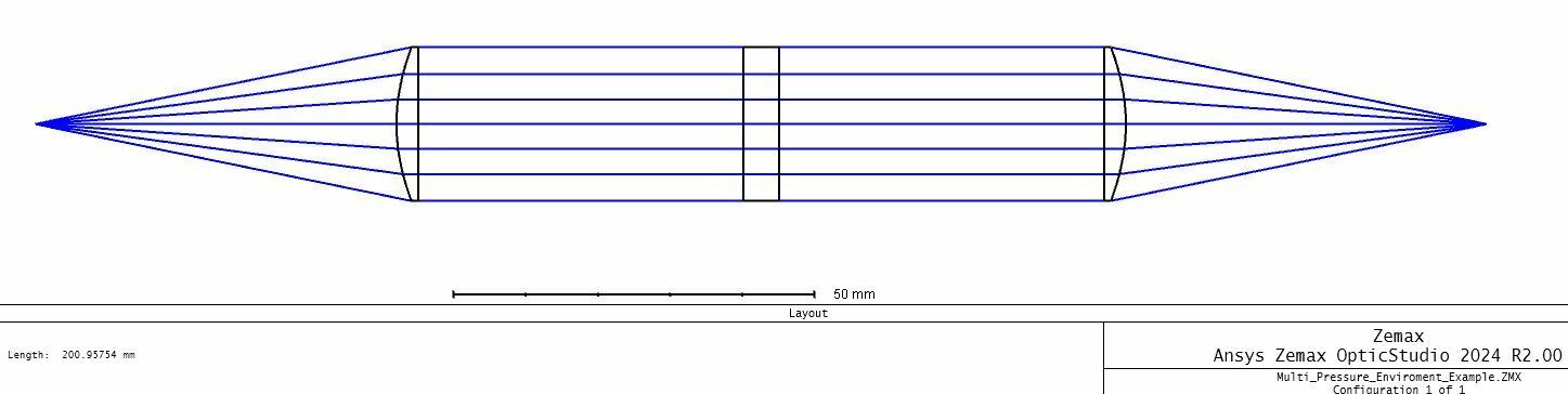
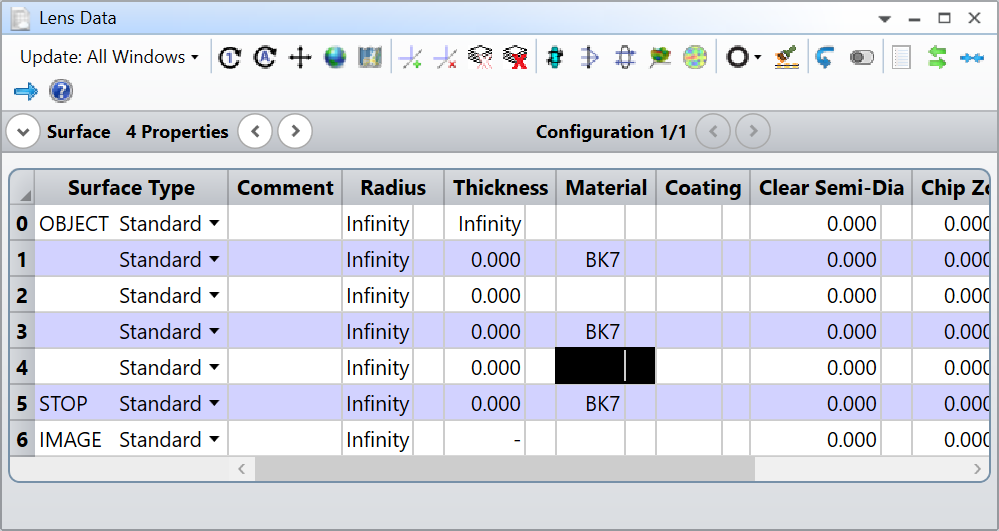
For the following configuration I have 8 surfaces (see images). I want surfaces 0-3 to be in a 1 ATM pressure environment. I then want surfaces 4-7 to be in a 0 ATM environment. I use the multi-config editor to set this up.

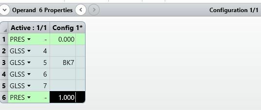
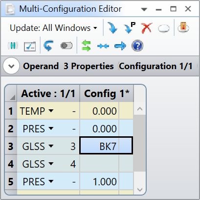
I first add a PRES operand to define a 0 ATM environment. I then list GLSS operands for surfaces 4 to 7 to state that I want these surfaces to be in the 0 ATM environment. I then add another PRES operand set to 1 ATM. My understanding is that this will set all other surfaces not listed in the MC to 1 ATM (surfaces 0 to 3). This final PRES operand also defines the global system pressure as seen in the environment tab in the system explorer. 

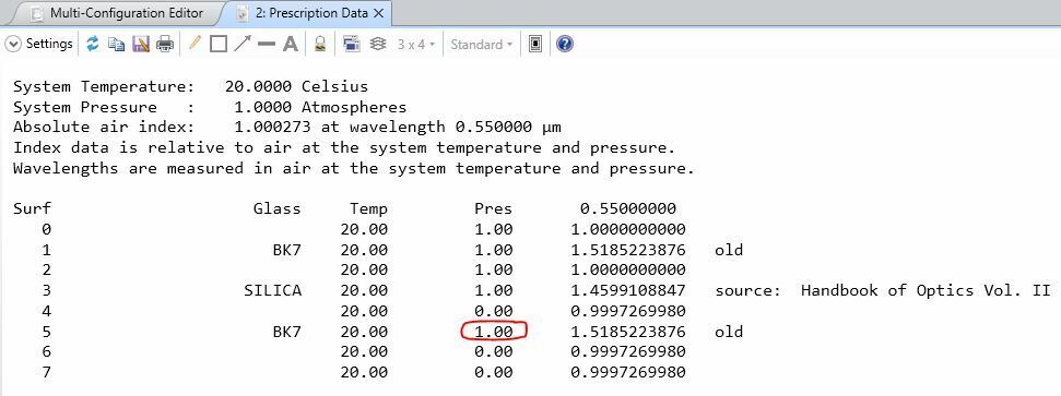
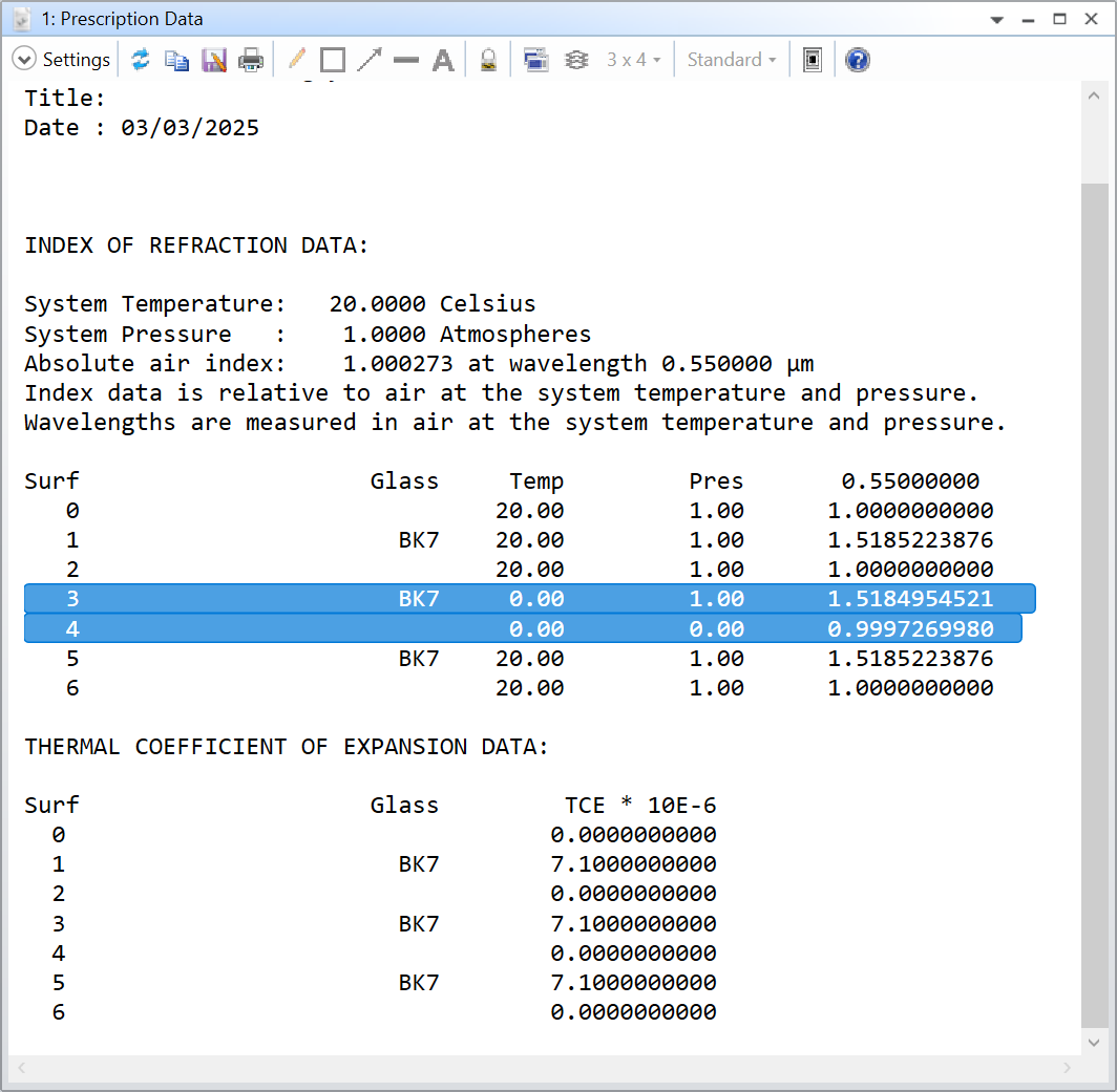
What’s odd to me, is when I look at index of refraction data in the prescription, surface 5, despite being in a 0 ATM environment, still has its index calculated at 1 ATM, while all other non-glass surfaces (4,6,7) are calculated at 0 ATM.

What I found is that all glass surfaces have their index defined at the global system pressure, and not whatever is defined in the MC editor. All non-glass surfaces will change their index to the specified pressure in the MC editor however.

What could I be missing here? And advice is appreciated, thanks.


3 replies

David.Nguyen
Luminary
Forum|alt.badge.img+2

@Anthony 


I am not too sure about my answer. It seems you need to make sure Setup..System Explorer..Environment..Adjust Index Data To Environment is checked.

Then, this is what I tested:

As you can see, for the air surface (4) the pressure is adjusted to 0.00, but not for the BK7 surface (3).

I don’t have time to check more thoroughly today, but I suspect maybe the pressure data is missing from the glass catalog for BK7. Is that possible?

I hope this helps in the meantime, take care,


David


David.Nguyen
Luminary
Forum|alt.badge.img+2

@Anthony 


I had a look at this topic:

And understood that there is no glass specific pressure data, instead the pressure comes into play only in the calculation of n_air. Therefore, it might be a bug.

Take care,


David


MichaelH
Ansys Staff
Forum|alt.badge.img+2
  • Ansys Staff
  • 342 replies
  • March 5, 2025

 ​@David.Nguyen  You are correct that pressure only affects the index of air; air is a compressible gas that changes density (and index) with a change in pressure.  The assumption OpticStudio makes is the density (and thus the index) or structure of a glass material doesn’t change.  Therefore, even if a really thin plate is modeled in OpticStudio, changing the pressure will not deform or change the radius of the plate.  As noted in the Help Files (my emphasis):

This means that air surfaces at different temperatures and pressures from the system temperature and pressure will have slightly lower or higher index...Remember, air at the system temperature and pressure is defined to be 1.0, all other indices are relative.


Note that all refractive index values are relative & scaled to the System TEMP & PRES; if your System Explorer > Environment > Pressure (ATM) is set to 1.0 and you use a PRES of 0 in the MCE, the Prescription Data will show a refractive index less than 1 (even though this is not physical).

If you look at an off-axis ray (5°) going through the plate and you don’t have any change in pressure, then the ray will enter and exit the plate at the same angle of incidence.  Therefore, all RAID operands for surface 1, 3, 5 will be 5°.  However, if you have a change in pressure on an air surface (S4), then the exiting ray from a previous surface will no longer exit at 5° and the AOI at the next surface (S5) will not be 5°.  So taking David’s example and looking at the RAID for S3 & S5 shows that the calculations are affecting the index of air as expected:

@Anthony to verify your MCE setup, I would suggest you use the Analyze > Rays & Spots > Single Ray Trace to verify you are getting expected changes at the expected surfaces.


Reply


Cookie policy

We use cookies to enhance and personalize your experience. If you accept you agree to our full cookie policy. Learn more about our cookies.

 
Cookie settings