
Grid Phase definition rule

  • January 30, 2020
  • 7 replies
  • 716 views

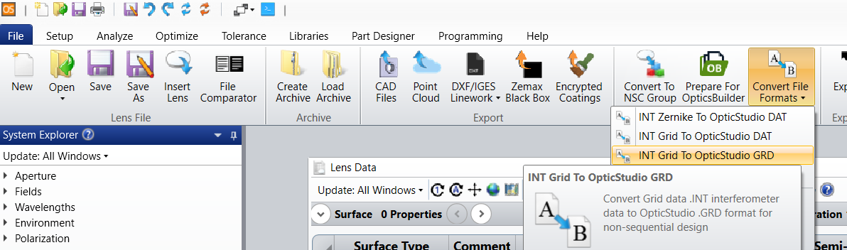
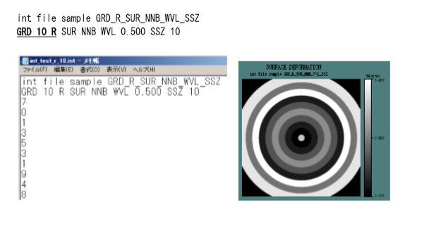
There is a INT function in CodeV to define the interferogram function of the surface.
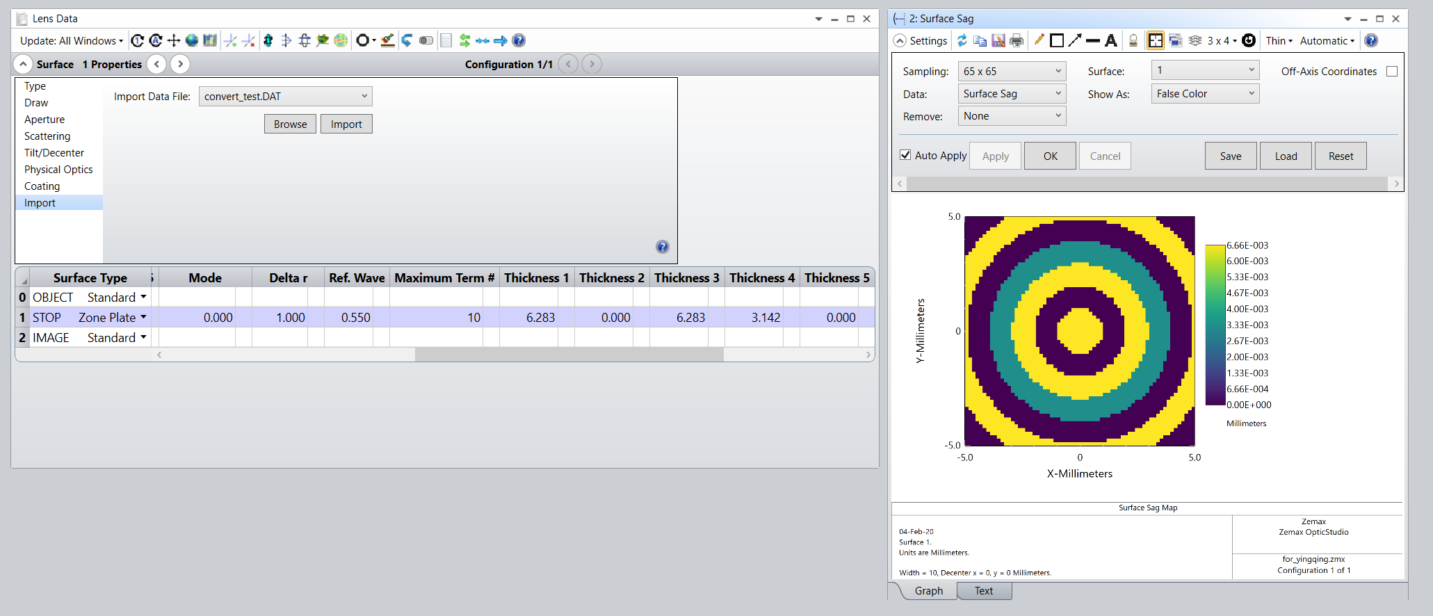
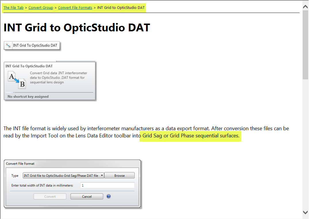
I guess probably "Grid Phase" in Zemax have the same function to define the phase surface by using DAT file. But don't know the rule for DAT file. And also, I want to define a circular phase changing surface, how to define in the DAT file?
Thank you
Did this topic help you find an answer to your question?

7 replies

Mark.Nicholson
Luminary
Forum|alt.badge.img+3
There's a utility for that in the File ribbon:


  • 0 replies
  • January 31, 2020
Thank you for your response. I have tried with this function, but the result I got is not good. And have no idea to define the circular surface. I have attached the converted file. Thank you so much

Mark.Nicholson
Luminary
Forum|alt.badge.img+3
Dear Yingqing,

I opened the INT file in Notepad, and there is not much there:
int file sample convert_test
GRD 10 R WFR WVL 0.543 SSZ 10
10
0
10
5
0
10
0
0
0
0

So I think the problem is in the INT file itself, it looks truncated. Do you know what this file is intended to look like?

  • 0 replies
  • February 3, 2020

Dear Mark,

Thank you for the tracking. The INT file is able to define the circular surface, it is not truncated.

For the second line, GRD 10 R, means it's circular surface, and it would divide the surface to 10 fold. Then listed data like 10,0,10,...,0 shows from center circular to the periphery area phase deformation.

From Zemax manual, I could see that circular definition is also supported in DAT file, but the conversion not going well. 

Could you check with that. 

Thank you so much.


Mark.Nicholson
Luminary
Forum|alt.badge.img+3

Hi Yingquing,

Which part of the manual are you referring to? The INT importer supports Zernike coefficients, and GRID data, but I don't see where it's claimed to support a radial distribution.

Are you expecting GRD 10 R to give you 10 datapoints that are then rotated through 180 degrees? If so, I don't think the INT imported supports that.

I think you do not need the Grid Phase surface. If you use the Zone Plate surface, I think this will give you what you want: radial zones of phase like so:


The Zone Plate surface can read the .DAT file directly. See the attached file for my example.


Mark.Nicholson
Luminary
Forum|alt.badge.img+3
Hey @TeamZemax,

The documentation on INT GRD to OpticStudio DAT feature is incomplete in this regard:


It makes no mention of the Zone Plate, or any other surfaces, that can Import .DAT files via the Import feature of the Surface Properties. Could someone raise a bug to get that fixed please?


  • 0 replies
  • February 7, 2020
Dear Mark,

Thank you so much for telling me the zone plate function and make the reference file. Radius zone of phase is what I want. 
But from the Zone plane definition, it could define the thickness of the surface but not the phase definition. 
I still want to define the surface like grid.png

And could use the SUR, WFR, FIL to seperately define the phase difference or field intensity difference. 
And the phase sag could be shown like Grid.PNG

Maybe Zone Plate can't reach this way? Or am I not too understanding about Zone plate use?

Best regards,
YQ Liu
 grid.png

Reply


Cookie policy

We use cookies to enhance and personalize your experience. If you accept you agree to our full cookie policy. Learn more about our cookies.

 
Cookie settings