Solved

Quarter wave plate with added phase error (Jone matrix)

  • September 11, 2024
  • 5 replies
  • 155 views

Isbjoern

Hello

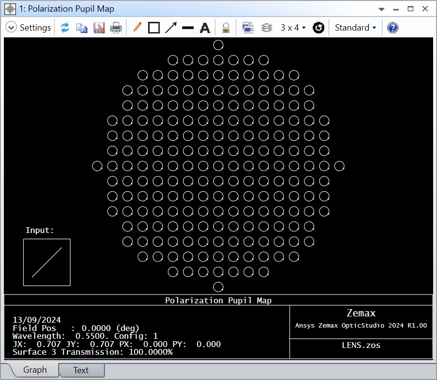
I want to simulate the effect of a quarter wave plate that creates an additional shift in the polarization of lets say 10° in a plarimeters. The polarimeter is comprised of a lens, collimating the polarized beam, a quarter wave plate, and an analyser plate. To determine the polarization state, the quarter wave plate is rotated azimutally by 180°. With the data I calculate the stokes parameter. It all works fine for the ideal case, but not for an added phase shift between both polarization states.
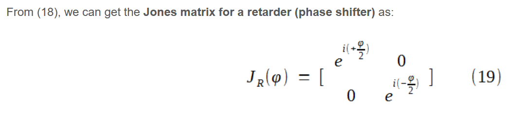
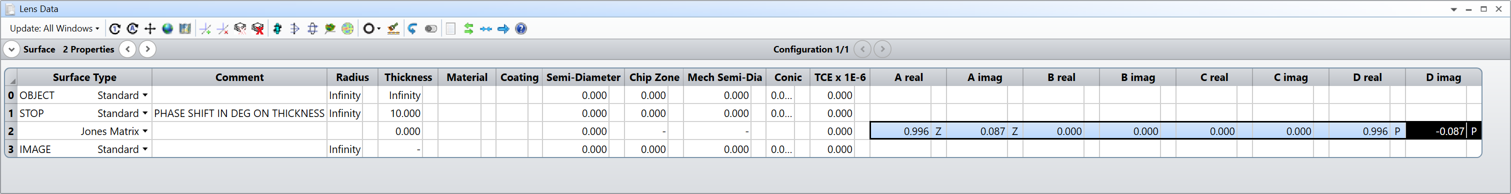
I am using the Jones matrix for the exact quarter wave plate in the form of:

A_real=1
A_img=0
D_real=0
D_img=1

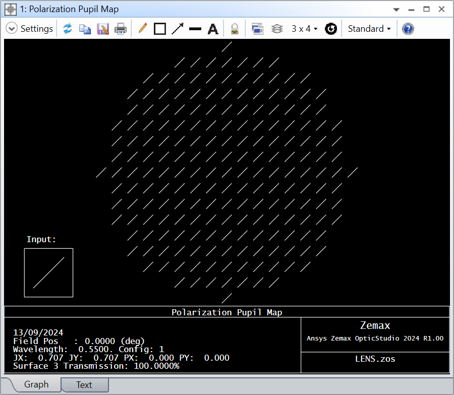
the result for this quarter wave plate is as expected. The result is the same when I use, for testing purpose, the non-factored version Jones matrix of the quarter wave plate:

A_real=0.707
A_img=0.707
D_real=0.707
D_img=-0.707

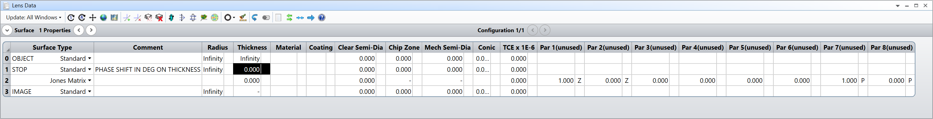
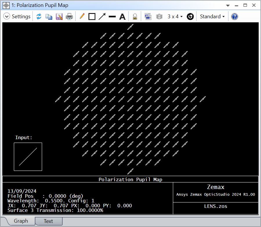
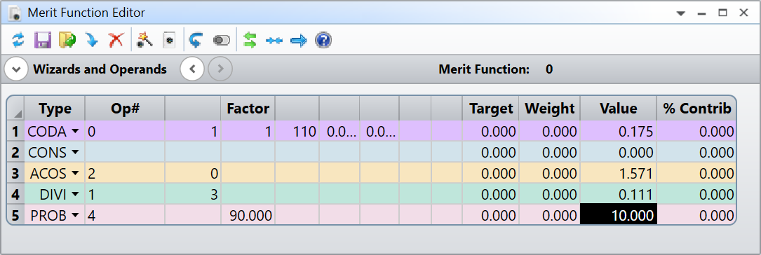
Now I add to the lambda/4 phase shift an additional shift of 10° in the Jone matrix, which results in the Jones matrix in Zemax notation:

A_real=0.573576
A_img=0.819152
D_real=0.573576
D_img=-0.819152

With this Jones matrix I get a lower system transmission (stokes parameter S0) than before and a polarization degree beyond 1 (stokes parameter S1).


Can anyone help with getting the correct Jones matrix for an “arbitrary” phase shift (e.g. retarder plate)?


Best answer by Isbjoern

@David.Nguyen 

Dear David,

indeed I used the same formula. The approach to separate both retardances in Zemax is doing the trick.

Interestingly, when I matrix multiply the Jone matricies of lambda/4 and 10° mathematically and put the result into Zemax I get a wrong result. The stokes parameter “polarization degree” (S2) is bigger than one.
When I put both retardances seperately into Zemax it works. I guess Zemax does some normalization in the background that it finally results in a polarization degree (S2) below 1. This is unexpected it should, from mathematical point of view, work both ways.
Anyhow, thank you for pointing out the solution!

View original
Did this topic help you find an answer to your question?

5 replies

David.Nguyen
Luminary
Forum|alt.badge.img+2
  • Luminary
  • 1099 replies
  • September 13, 2024

@Isbjoern


I’ve been doing some Jones calculations with OS lately, but I’m not an expert at all. What’s your matrix definition for the retarder (10° shift)?

I’m using this formula, from this article:

To avoid calculation errors, I recommend letting OS compute the matrix product, i.e. define one Jones Matrix surface per matrix you have (1 quarter-wave plate, 1 retarder, 1 polarizer or analyzer). Also, I prefer to just have a dummy surface where I can change the parameter of interest, such as φ in Eq. 19 above, and let OS calculate the matrix using ZPL and pickup solves. Here is how I would setup the retrarder:

And I have the following ZPL solves on the A real/imag columns:

CONS_PI = 2 * ACOS(0)

phi_deg = THIC( SURC("PHASE SHIFT IN DEG ON THICKNESS") )
phi_rad = phi_deg / 180 * CONS_PI

SOLVERETURN COSI( phi_rad / 2 )
CONS_PI = 2 * ACOS(0)

phi_deg = THIC( SURC("PHASE SHIFT IN DEG ON THICKNESS") )
phi_rad = phi_deg / 180 * CONS_PI

SOLVERETURN SINE( phi_rad / 2 )

It is not the most optimal in terms of computation (you could do the deg to rad conversion once elsewhere), but I hope you get the point.

It seems to work for me. When the Thickness of Surface 1 is 0 (or 0°):

When the Thickness of Surface 1 is 10 (or 10°):

The retardance measured with CODA in the Merit Function also gives 10°:

And the Jones Matrix looks like so:

Last confirmation was a retardance of 90° since we expect circular polarization:

I hope this helps.

Take care,


David


Isbjoern
  • Author
  • Single Emitter
  • 2 replies
  • Answer
  • September 13, 2024

@David.Nguyen 

Dear David,

indeed I used the same formula. The approach to separate both retardances in Zemax is doing the trick.

Interestingly, when I matrix multiply the Jone matricies of lambda/4 and 10° mathematically and put the result into Zemax I get a wrong result. The stokes parameter “polarization degree” (S2) is bigger than one.
When I put both retardances seperately into Zemax it works. I guess Zemax does some normalization in the background that it finally results in a polarization degree (S2) below 1. This is unexpected it should, from mathematical point of view, work both ways.
Anyhow, thank you for pointing out the solution!


David.Nguyen
Luminary
Forum|alt.badge.img+2
  • Luminary
  • 1099 replies
  • September 13, 2024

@Isbjoern


No worries, its good to know that the product doesn’t work when done outside OS though. I’ve made a sort of polarimeter recently, although not with a quarter-wave plate and in the context of polarization-resolved SHG. DM me if you’re interested to share about your experience making such a device.

Take care,


David


Isbjoern
  • Author
  • Single Emitter
  • 2 replies
  • September 13, 2024

Sorry, I marked my post as answer. It should have been your post. Do you know how to change it? You should get the credit for it.


David.Nguyen
Luminary
Forum|alt.badge.img+2
  • Luminary
  • 1099 replies
  • September 13, 2024

@Isbjoern 


Don’t worry about it. As far as I know, only Ansys personnel can do it. Your answer also has meaningful information in it 😊

Have a great weekend,


David


Reply


Cookie policy

We use cookies to enhance and personalize your experience. If you accept you agree to our full cookie policy. Learn more about our cookies.

 
Cookie settings