Solved

Batch Raytracing With the ZOS-API MATLAB dll


I started modifying the boilerplate code included on this page:


https://support.zemax.com/hc/en-us/articles/1500005576882


Looking through the ZOS-API help from the Programming Tab in OpticStudio I can tell that there are some differences between the way the code is implemented in the .dll versus the way it is described in the help files. How do I access the API for the methods and classes inside the .dll file? 

Best answer by Brian.Catanzaro

I suggest that you make sure that your model does exactly what you think it does.  If I were faced with this challenge, I would

  1. Trace a single ray using the GUI that has vignetting. 
  2. Verify that the GUI ray trace shows vignetting.
  3. Trace the exact same ray in Matlab.
  4. Verify that vignetting occurs

Repeat the above for a few “good rays” that don’t vignette.

I would do the same for the error code.

Once you check that (or if you have questions regarding how to do the above), get back to me and I’ll set up an example that checks your code.

View original
Did this topic help you find an answer to your question?

7 replies

Forum|alt.badge.img+2

HI @devin.vega@l3harris.com!

As it says in the article, the DLL is designed to hand-off time intensive for loops from MATLAB or Python, which handles this very inefficiently.

You will have to look at the examples of the articles to see the methods you can access. For example, this example MATLAB_BatchRayTrace_Direct.m – (SEQ Direct) shows how to use the function ReadDirectUnpolData from the RayTrace.dll (DirectUnpol.cs). 


Brian.Catanzaro
Fully Spectral
Forum|alt.badge.img+4

I use Matlab with the ZOS-API frequently to automate sequential and non-sequential traces.  I also use it to read the ray database files after they are stored.  Perhaps I can help.

Can you describe more specifically what you want to do and I may be able to provide a code snippet that is effective?


Hi @Brian.Catanzaro , I am tracing a batch of rays through a lens using the CreateDirectPol method and trying to exclude the vignetted rays. I am then plotting the locations of the remaining rays at the image plane. I have used the vignetteCode returned by the function to exclude rays that were vignetted and checked for any error codes to exclude any more rays. The problem is that I am sometimes getting no vignetteCode or error code when I know from my Zemax ray trace sanity checks that all rays should be vignetted. For context, I am raytracing in sequential mode through a double pass system. Below is a subset of the raytrace code I am using. I was hoping to find out whether there are any further tools available to allow me to determine whether the ray was vignetted, experienced an error, missed the system entirely, or what have you. Thank you for any help you might have.


    % Set up Batch Ray Trace    
    % creates batch raytrace in API
    raytrace = TheSystem.Tools.OpenBatchRayTrace();
    % creates batch raytrace in API
    % Performs a batch unpolarized ray trace, using direct pupil
    % coordiantes; Format is CreateDirectPol (int MaxRays, RaysType
    % rayType, double Jx, double Jy, double phax, double phay, int
    % startSurface, int toSurface)
    RayTraceData = raytrace.CreateDirectPol(total_rays_in_both_axes, ZOSAPI.Tools.RayTrace.RaysType.Real, 0,0,0,0,startSur,endSur);

    % offloads processing to C# dll
    NET.addAssembly(strcat(pwd, '\RayTrace.dll'));
    import BatchRayTrace.*;

    % Call the function ReadNormUnpolData from dll
    dataReader = ReadDirectPolData(raytrace, RayTraceData);
    % The variable dataReader can now use all the functions defined in the DLL
    dataReader.ClearData();

    x_field = 0;    % angle in degrees
    y_field = tempAngle;    % angle in degrees

    x_field = x_field * pi/180;
    y_field = y_field * pi/180;

    xOffset = imageDist * tan(x_field * 180 / pi);
    xstep = epd/(max_rays - 1);
    xin = -epd/2 - xOffset : xstep : epd/2 - xOffset;
    yOffset = imageDist * tan(y_field * 180 / pi);
    ystep = xstep;
    yin = -epd/2 - yOffset : xstep : epd/2 - yOffset;

    [Xin,Yin] = meshgrid(xin,yin);
    Xin = reshape(Xin,[numel(Xin),1]);
    Yin = reshape(Yin,[numel(Xin),1]);
    Zin = zeros(numel(Xin),1);

    l = cos(pi/2 - x_field);
    m = cos(pi/2 - y_field);
    n = sqrt(1 - l^2 - m^2);

    l = l*ones(numel(Xin),1);
    m = m*ones(numel(Yin),1);
    n = n*ones(numel(Zin),1);

    dataReader.AddRay(wave, Xin, Yin, Zin, l, m, n);

    % Configure the maximum number of segments to read at one time.
    % Note that this is a tradeoff between speed and memory usage
    rayData = dataReader.InitializeOutput(max_rays);    %command to initiate the ray trace
    isFinished = false;
    totalRaysRead = 0;
    maxRays = 0;

    % initialize output variables
    x = [];
    y = [];
    theVig = [];
    lo = [];
    mo = [];
    no = [];
    pow = [];
    errs = [];

    while ~isFinished
        % fill the next block of data
        readSegments = dataReader.ReadNextBlock(rayData);

        if readSegments == 0
            isFinished = true;
        else
            % Note - MATLAB arrays are 1-based, however .NET arrays are 0-based, so we have to be carefull...
            maxRays = max(rayData.rayNumber.double);
            xData = rayData.xo.double;
            yData = rayData.yo.double;
            ZData = rayData.zo.double;
            lData = rayData.lo.double;
            mData = rayData.mo.double;
            nData = rayData.no.double;
            vigData = rayData.vignetteCode.int32;
            tens = rayData.intensity.double;
            thisErr = rayData.ErrorCode.int32;

        end

        if totalRaysRead >= maxRays
            isFinished = true;
        end
    end

    if maxRays > 0
        x = [x xData(1:maxRays)];
        y = [y yData(1:maxRays)];
        theVig = [theVig vigData];
        lo = [lo lData];
        mo = [mo mData];
        no = [no nData];
        pow = [pow tens];
        errs = [errs thisErr];
    end

    % select the unvignetted rays
    x = x(~theVig);
    y = y(~theVig);
    power = pow(~theVig);

    lo = lo(~theVig);
    mo = mo(~theVig);
    no = no(~theVig);


Brian.Catanzaro
Fully Spectral
Forum|alt.badge.img+4

I suggest that you make sure that your model does exactly what you think it does.  If I were faced with this challenge, I would

  1. Trace a single ray using the GUI that has vignetting. 
  2. Verify that the GUI ray trace shows vignetting.
  3. Trace the exact same ray in Matlab.
  4. Verify that vignetting occurs

Repeat the above for a few “good rays” that don’t vignette.

I would do the same for the error code.

Once you check that (or if you have questions regarding how to do the above), get back to me and I’ll set up an example that checks your code.


MichaelH
Ansys Staff
Forum|alt.badge.img+2
  • Ansys Staff
  • 342 replies
  • May 19, 2023

Hi Devin,

A few suggestions: 

  • It looks like you’re defining your fields in degrees and then you’re taking the tangent of the field; however, you are not converting from degrees to radians (pi / 180) but rather the inverse of the conversion (180 / pi)
  • For the direction cosines, you are not converting from degrees to radians
  • It looks like you’re simply sending in collimated light to a uniform grid at the Entrance Pupil.  This is exactly what the CreateNormPol() does, so there isn’t a need to use direct ray tracing.  Unless there is a really good reason to use direct ray tracing, normalized ray tracing is recommended because OpticStudio already has the code in place to ensure rays make it through the system and Ray Aiming does not work with direct ray tracing; using a direct ray is very powerful but is often difficult to get correct.

To continue Brian’s debugging suggestions, I would also look at tracing a single ray in the ZPL and check for vignetting:

# assume 'epd' is entrance pupil diameter
epd = OPEV(OCOD("EPDI"), 0, 0, 0, 0, 0, 0)

# assume 'imageDist' is the image distance and there is only a single row
imageDist = THIC(NSUR() - 1)

PI = 2 * ACOS(0)

y_field = 10  # random field value
yOffset = imageDist * TANG(y_field * PI / 180)

Xin = -epd  / 2 # with 'x_field = 0', there is no xOffset
Yin = -epd / 2 - yOffset
Zin = 0

Lin = 0		# we have no x-component
Min = COSI(PI / 2 - y_field * PI / 180)
Nin = SQRT(1 - Lin*Lin - Min*Min)

# run the direct ray trace
RAYTRACEX Xin, Yin, Zin, Lin, Min, Nin, 0, PWAV()

# for for errors or vignetting
FOR i = 0, NSUR(), 1
	IF RAYE(i) != 0 THEN PRINT "Error at surface : " , i
	IF RAYV(i) != 0 THEN PRINT "Vignetting at surface : ", i
NEXT

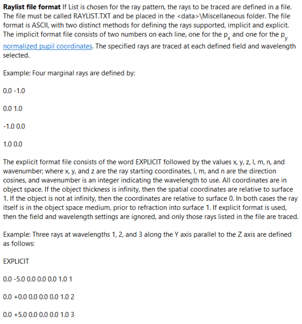
I would also suggest using the RAYLIST.txt and use the EXPLICIT keyword to show a single direct ray on a 3D Layout plot:


Brian.Catanzaro wrote:

I suggest that you make sure that your model does exactly what you think it does.  If I were faced with this challenge, I would

  1. Trace a single ray using the GUI that has vignetting. 
  2. Verify that the GUI ray trace shows vignetting.
  3. Trace the exact same ray in Matlab.
  4. Verify that vignetting occurs

Repeat the above for a few “good rays” that don’t vignette.

I would do the same for the error code.

Once you check that (or if you have questions regarding how to do the above), get back to me and I’ll set up an example that checks your code.

Hi Brian. Thank you so much for your response. In looking up how to go about your suggestions, I found that I could open the C# files that were packaged with the examples in Visual Studio to read the function description. That helped a lot and I was able to solve my issues. Thanks again! 


MichaelH wrote:

Hi Devin,

A few suggestions: 

  • It looks like you’re defining your fields in degrees and then you’re taking the tangent of the field; however, you are not converting from degrees to radians (pi / 180) but rather the inverse of the conversion (180 / pi)
  • For the direction cosines, you are not converting from degrees to radians
  • It looks like you’re simply sending in collimated light to a uniform grid at the Entrance Pupil.  This is exactly what the CreateNormPol() does, so there isn’t a need to use direct ray tracing.  Unless there is a really good reason to use direct ray tracing, normalized ray tracing is recommended because OpticStudio already has the code in place to ensure rays make it through the system and Ray Aiming does not work with direct ray tracing; using a direct ray is very powerful but is often difficult to get correct.

To continue Brian’s debugging suggestions, I would also look at tracing a single ray in the ZPL and check for vignetting:

# assume 'epd' is entrance pupil diameter
epd = OPEV(OCOD("EPDI"), 0, 0, 0, 0, 0, 0)

# assume 'imageDist' is the image distance and there is only a single row
imageDist = THIC(NSUR() - 1)

PI = 2 * ACOS(0)

y_field = 10  # random field value
yOffset = imageDist * TANG(y_field * PI / 180)

Xin = -epd  / 2 # with 'x_field = 0', there is no xOffset
Yin = -epd / 2 - yOffset
Zin = 0

Lin = 0		# we have no x-component
Min = COSI(PI / 2 - y_field * PI / 180)
Nin = SQRT(1 - Lin*Lin - Min*Min)

# run the direct ray trace
RAYTRACEX Xin, Yin, Zin, Lin, Min, Nin, 0, PWAV()

# for for errors or vignetting
FOR i = 0, NSUR(), 1
	IF RAYE(i) != 0 THEN PRINT "Error at surface : " , i
	IF RAYV(i) != 0 THEN PRINT "Vignetting at surface : ", i
NEXT

I would also suggest using the RAYLIST.txt and use the EXPLICIT keyword to show a single direct ray on a 3D Layout plot:


Thank you Michael! I don’t know how I overlooked those conversion issues! I did eventually get the rest working. Cheers!


Reply


Cookie policy

We use cookies to enhance and personalize your experience. If you accept you agree to our full cookie policy. Learn more about our cookies.

 
Cookie settings