Hi Erin,
This is fantastic. Can you clarify how the high order deformations ‘know’ how to correct the spherical? That implies a feedback loop.
Ah - no, it’s not that fancy. I just manually calculated the dZ needed to convert the spherical surface into an asphere, and wrote it into my FEA data file. Outside of the rigid-body motions, the only change to the surface shape is this dZ data; otherwise, dX and dY deformation vectors are 0.
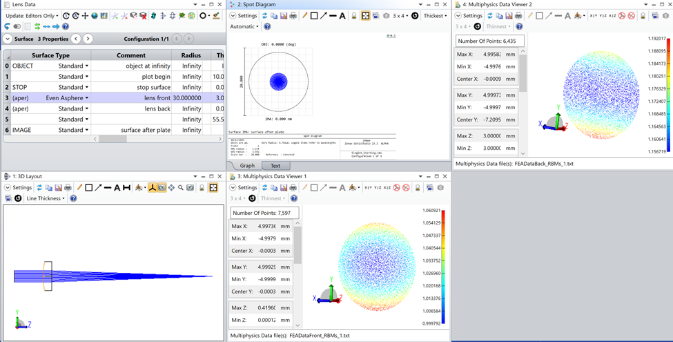
I should have reminded everyone in the article that the deformation data format is just:
X Y Z dX dY dZ, for every point in the FEA data set. We usually use about 10k points per inch of diameter or so.
Thanks! So how does the spherical get corrected? As you say, it’s unusual for deformations to improve the lens, so how is that happening physically?
I calculate the dZ deformation like this: the lens starts out with a spherical front surface. To correct the spherical aberration in the lens, I can optimize to find the aspheric terms needed on the front surface: rho^4, rho^6, rho^8, etc. I calculate dZ = (sag of the asphere - sag of the sphere), and write the FEA data out. When I apply the FEA data, then, to the original lens, it just adds a dZ shift to convert the sphere to the asphere that I want. (It’s all very manual.)
The combined effect of the aspheric terms is to make the surface flatter as you move toward the edge of the part, compared to the sphere. So where the sphere has constant curvature as a function of radial position, the deformed surface has a curvature that decreases as you move radially outward.
(But let me know if I misunderstood the question!)
I think it may be me who misunderstood. In your original post you said “Also, the higher-order deformations on the front of the lens convert the spherical front surface to an asphere, to correct the spherical aberration in the system.” (My emphasis.) This implied to me some way in which the deformations ‘knew’ how to adjust themselves to produce a desired optical outcome.
I was thinking of something similar to tolerancing, in which we adjust the compensator to achieve best focus and can find a better spot than the nominal design, but this requires an adjuster and a measurement system capable of knowing what best focus is.
In this case, is the correction of spherical coincidental, rather than intentional?