This thread is dedicated to the upcoming webinar: Modeling a Lidar System in OpticStudio: Characterizing Range for Lidar Systems. Any questions received during the webinar will be responded to as a reply on this thread. Feel free to post your own questions! The speaker will be notified and will respond as long as the thread is still open.

Be sure to subscribe to this thread if you want to see additional discussion regarding this webinar topic. The thread will be open to new replies for a limited time following the event.


>The webinar has concluded]


Webinar details

Date: Thursday, October 27th

Time: 6:00 - 6:45 AM PDT | 11:00 - 11:45 AM PDT

Presenter: Angel Morales, Senior Application Engineer

Abstract:

Modeling a Lidar in OpticStudio: Characterizing Range for Lidar Systems. For lidar systems, a key specification is the range at which the lidar can detect a positive return signal. This characteristic is determined by several factors, such as the energy contained in the light pulse sent by the lidar, the response of the detector used in the system, the transmission of the optics used, and more. In this webinar, we will explore approaches in system setup using OpticStudio that can enable users to better understand the range of their lidars, allowing for quick system validation in ideal working conditions as well as non-ideal edge cases.

Watch the recording!

A recording of the webinar may be found at the following link: Modeling a Lidar System in OpticStudio: Characterizing Range for Lidar Systems


Is there available the shown zemax file?


Hi @Theodoros.Anagnos -- thanks for your post! Yes, the files are available for sharing. Apologies for the delay on my part in posting them, but I have attached the three demonstration files in this .ZIP folder for reference.

In addition, below, I will be posting answers to a few questions that came in which we did not address yet. Thanks again to everyone who attended the webinar, and please feel free to submit additional questions here!


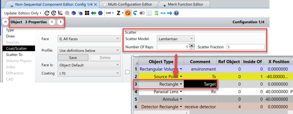
Q: Did you define your target rectangle to be lambertian? and how? Thanks!

A: Hello! Yes, my scattering rectangle was defined with Lambertian scattering. This can be set in the Object Properties…Coat/Scatter tab as shown below:


Q: Are you considering atmospheric scattering or just absorption?

A: In this model, I just looked at the absorption of the intermediate distance between the lidar and the target to determine the strength of the receiving signal. OpticStudio also supports atmospheric scattering modeling through the use of a Mie scattering model. Note that this kind of scattering (Bulk Scattering) in OpticStudio is separate from the surface scattering used to define the Lambertian surface.

For some more information on bulk scattering in OpticStudio, you can take a look at these articles:


@Andy.Hölling 

Q: In your last example with the attenuation in air, why was only the source set to be "Inside Of" the "Environment Box"? Shouldn't the target, receiver lens and detector be set to be "Inside of" the Environment box?

A: The Inside Of parameter is a setting just for Source Objects that start in some medium other than air. This is to ensure that OpticStudio initializes the rays in the correct index – otherwise, ray trace errors will occur and results will be inaccurate.

Geometry objects, like lenses, volumes, and CAD parts, have any material properties of overlapping regions determined by the nesting rule. The nesting rule means that for any two geometry objects that occupy the same space, whichever object is listed later in the Non-Sequential Component Editor is the one that defines the composition of the overlap. We have an article discussing the general approach of defining a background medium here: Can I define a background material other than air? – Knowledgebase (zemax.com)

I should mention there is a bit of a special consideration for sources which are initialized near Boolean Native objects, but I’ll refer interested readers to the Help File page at The Setup Tab > Editors Group (Setup Tab) > Non-sequential Component Editor > Non-sequential Geometry Objects > Boolean Native (specifically in the Placing sources inside the Boolean Native object section) for more details on that.


Q: what was the name of the first equation again. Pr = sigma * ....?

A: Thanks for the question! I am not sure if the equation has a specific name, as it was a derivation for the received power on a detector from a transmitted pulse making some roundtrip propagation. I referenced the journal article Review of ladar: A historic, yet emerging, sensor technology with Rich Phenomenology, which should be open access on the SPIE website: Review of ladar: a historic, yet emerging, sensor technology with rich phenomenology (spiedigitallibrary.org)


Reply