[Webinar] Cell Phone Lens: The Fundamentals Behind the Optical System Design [Q&A]


Userlevel 6
Badge +2

This thread is dedicated to the webinar: Cell Phone Lens: The Fundamentals Behind the Optical System Design. Any questions received during the webinar will be responded to as a reply on this thread. Feel free to post your own questions! The speaker will be notified and will respond as long as the thread is still open.

Be sure to subscribe to this thread if you want to see additional discussion regarding this webinar topic. The thread will be open to new replies for a limited time following the event.


This event has closed. Click here to watch the recording.


Presenter: Katsumoto Ikeda, Manager Application Engineering

Abstract:

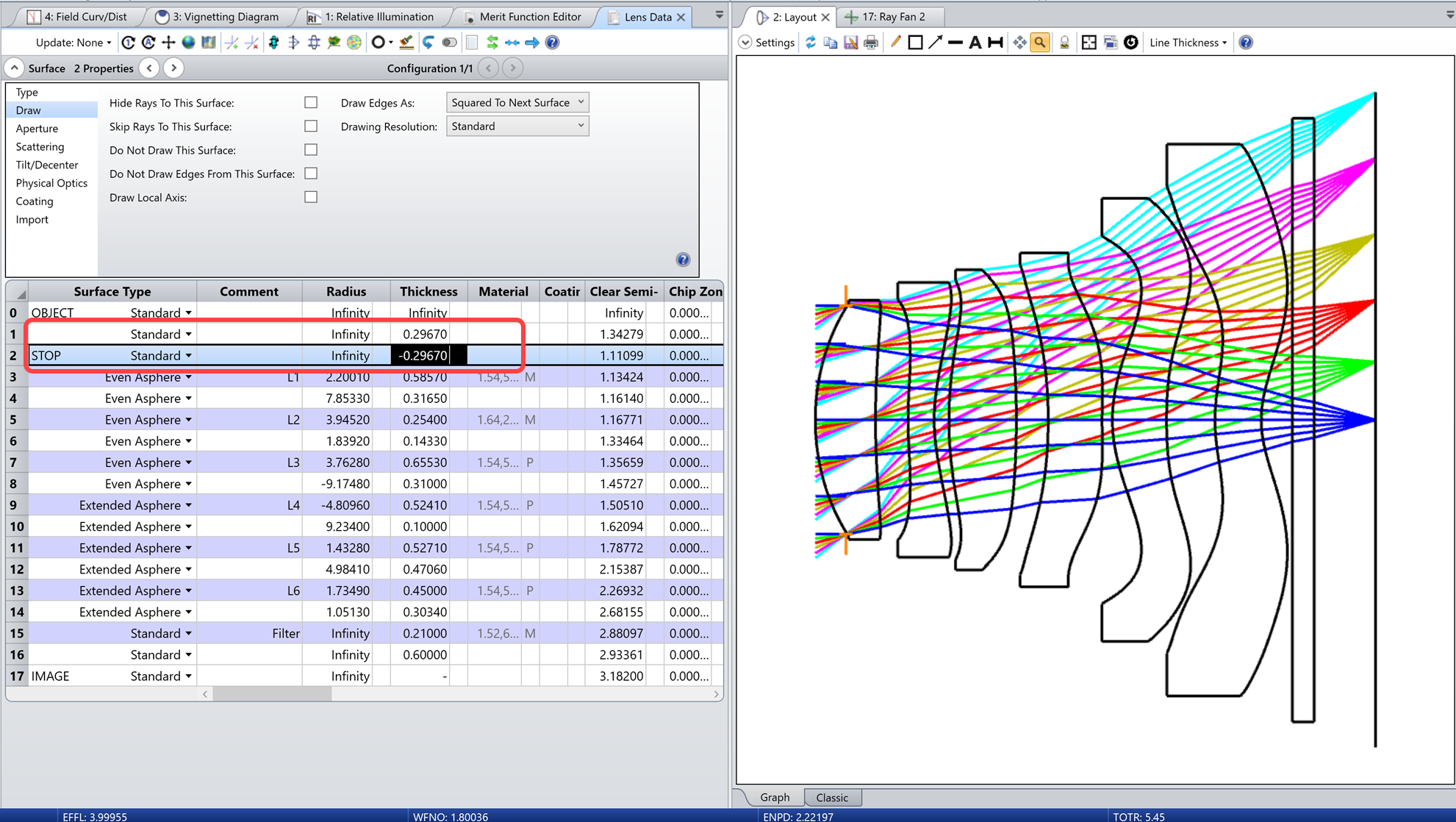
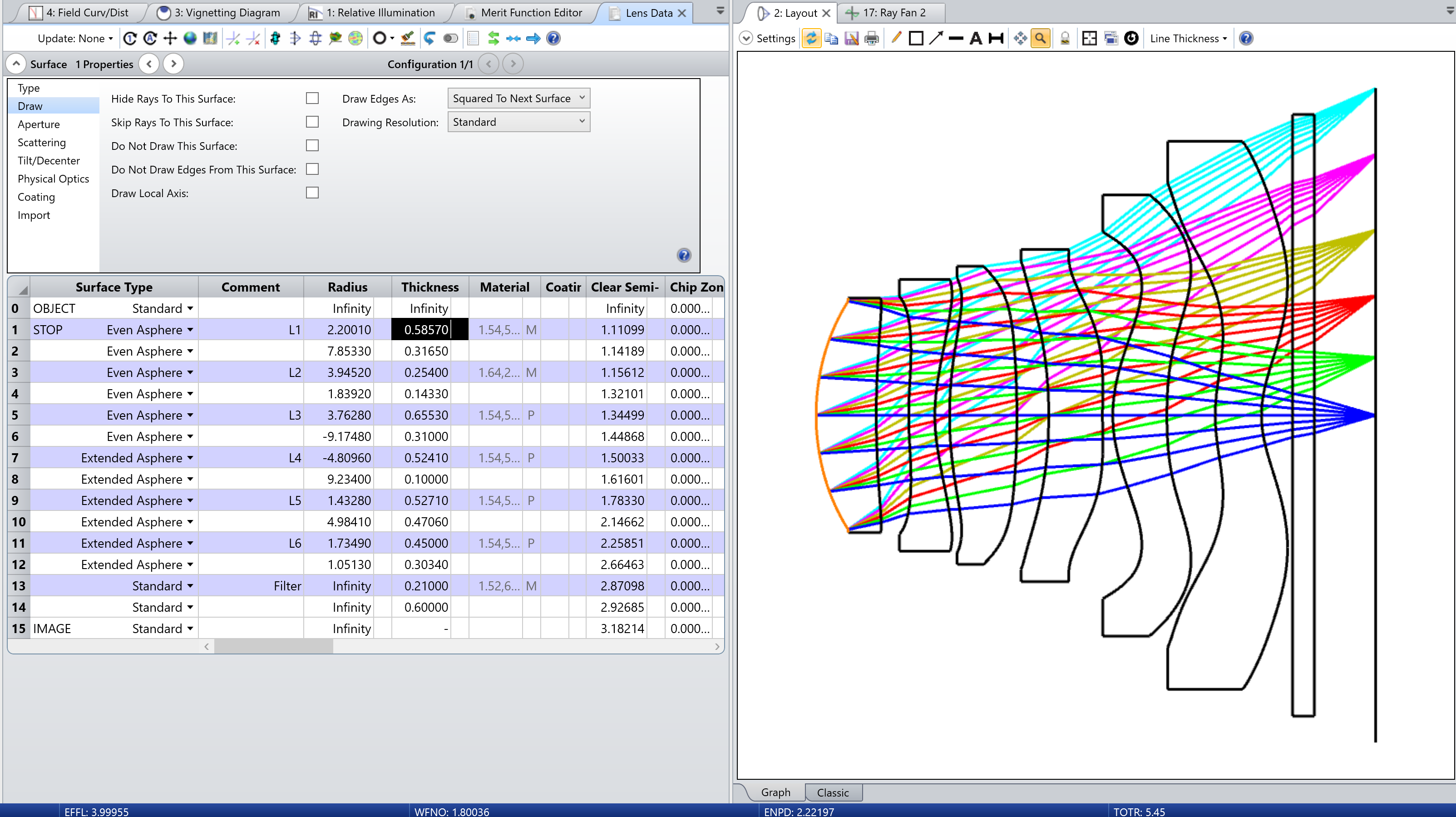
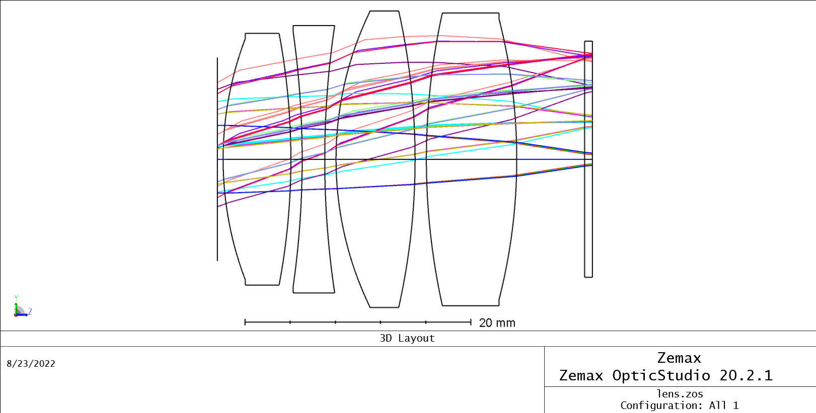
The methods and tools for optical lens design have been evolving for over a hundred years, and today we have modern computing software to assist our lens design process. In particular, the degrees of freedom that plastic lenses provide, coupled with the computational power of today's computers with software have made the optical lens design of plastic optics more advanced than ever before. One example of a complex optical design using plastic optics is the mobile phone lens. The design process of a modern mobile phone lens used in smartphones is our topic for this presentation. We will break down the optical lens design process and identify the characteristics of a typical mobile phone lens. We will investigate various procedures of the lens design process. We start with the concept of a cell phone design, what is important and how to optimize from an optical point of view.

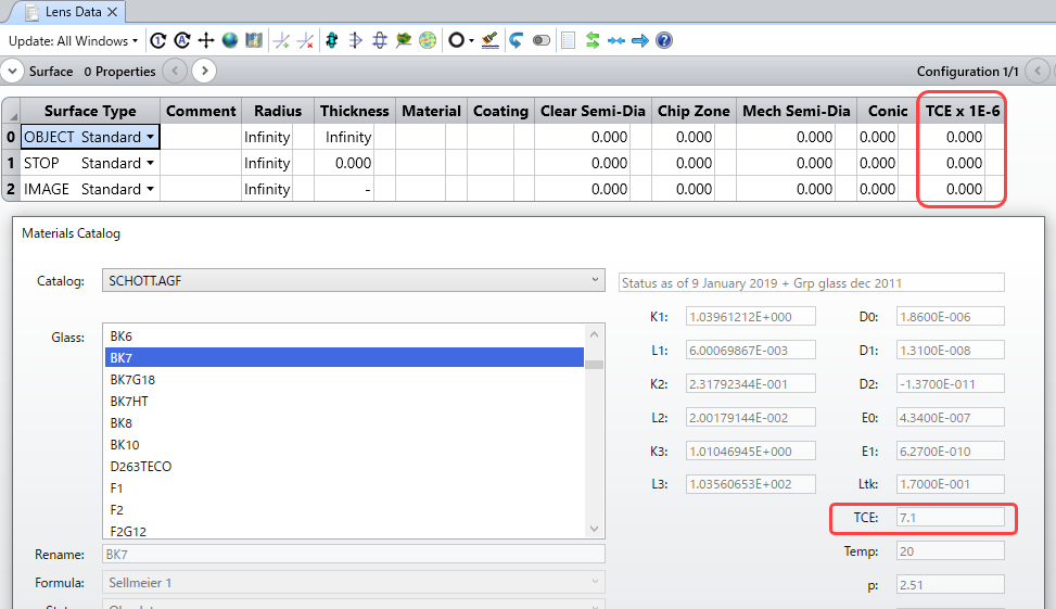
Following the optical design, we will investigate the mechanical design particular to cellphone designs, and also add the housing of the cellphone lens, to ready the design for production via optical simulation with mechanical parts. Finally, we will start to consider the thermal and structural effects of the lens to analyze environmental factors. The entire process will be a guide to virtual prototyping of optical lens design so that we can effectively ready our lens design into production quickly and more efficiently.

Katsumoto Ikeda 1 year ago

Q: Will the recording be available later?

A: Yes, the webinar is available online, please find the direct link below:
Cell Phone Lens: The Fundamentals Behind the Optical System Design – Zemax

-Kats

View original

This topic is closed to new comments

15 replies

Userlevel 4
Badge

Hello,

Thank you everyone for joining this webinar!

In this thread below, we will answer the questions we didn’t get to during the live event.

If you have any further questions, please ask!

Katsumoto Ikeda

Userlevel 4
Badge

Q: Will the recording be available later?

A: Yes, the webinar is available online, please find the direct link below:
Cell Phone Lens: The Fundamentals Behind the Optical System Design – Zemax

-Kats

Userlevel 4
Badge

Q: On the plastic materials - is there a better choice of material combination to choose for better thermal stability of the design?  / which operands are most useful to control aspherical surfaces during optimization? 

A:

1) Due to the number of lenses we need to produce, plastic is the default choice. There are some plastics developed that have a slightly better thermal stability, but they can't beat glass.
2) That is the problem... there are no operands that can control aspherical coefficients from acting badly. 

-Kats

Userlevel 4
Badge

Q: In beginning, maybe slide 7 or so, you show an optical ray trace model for a "typical" cell phone lens.  It looks like the aperture stop is on a curved surface where this curved surface goes inside of the front lens.  How is the possible and how can this be defined in Zemax.  Why would you want to do this?

A: Thank you for the question. The lens is actually an iPhone lens from the iPhone 5 or so.  I agree that with the number of rays of the pupil, it can look like the stop is curved and inside the first lens. The lens has two dummy surfaces, where the dummy surface applies to the inner rays but not the outermost rays of the pupil (you can see this by looking at the marginal rays for each field). The patent illustrates the stop surface with a +/- thickness to bring the rays forward and then backward. This is usually done to evaluate performance for tolerancing purposes. It gives more control to the bundle of rays other than the marginal rays to evaluate performance.
 
?name=image.png
 
If we delete the two +/- surfaces, you can see the centroid rays change, but not the P=1.00 and P=-1.00 rays at the extremities. The performance doesn't change at all for the nominal design. 
?name=image.png
You can find more details in the patent document. 
https://patents.google.com/patent/US20170299845A1/en


Also, if you are interested, please join the discussion related to this topic in a separate community post.


I hope this helps! 
 
-Kats

Userlevel 4
Badge

Q: What sort of optomech is necessary to keep such a large number of optics aligned? 
A: Typically we set the lenses into a molded plastic housing that is designed around the optics. Doesn't usually happen on the first try. 

-Kats

Userlevel 1

Hello Katsumoto,

Thanks for giving the webinar. It was very interesting!

Are you familiar with designs when each field enter to the system from different stop:


Trying to optimize when using one ciruclar stop for all fields, fail to converge to anything that works.

Moreover these systems are usally in the range of ~2 WFNO and larger than 50 degree FOV.

Is there any tips that you can give?


Thanks,

Nadav

Userlevel 4
Badge

Q: Can Kerry indicate what is the minimum quantity of lenses to access molded plastic technology?
A: Kats here 😀 It depends on the size and shape, but each lens if made individually a can be a few $100 to $1000. A mold can cost upwards of a few $100,000, and each lens is sold at a few cents. My back of the napkin math tells me that if you are making 100~1000 lenses, you are better off making lenses individually. So let's say a few thousand lenses is the threshold for making a mold. iPhones are made by the millions, so it makes sense to make a mold. 

There is an interesting webinar on aspheres for your reference.

Aspheres: designed to be made - advice from a manufacturer

-Kats

Userlevel 4
Badge

Q: Is there an advantage of using Even aspheres from a raytracing optimization perspective? Does Zemax optimize Even aspheres better and faster than Q-type aspheres?
A: There is a chance that Zemax optimizes Even Aspheres better, if we are simply looking at convergence of the Merit Function. But the convergence of the Merit Function does not necessarily mean that the optical system is reaching a solution. 

-Kats

Userlevel 4
Badge

Q: Can you describe how to compensate for thermal irregularities with the design?

A: Yes! Please refer below

STOP Analysis of high-power laser systems - part 5

From Concept to CubeSat Part 4: Using the Ansys Zemax Software Suite to Develop a CubeSat System

-Kats

Userlevel 4
Badge

Q: I would be interested to know how big  a value of K is too big.
A: You can do some math to see where K becomes dominant, but for typical cellphone optics, +/- 5~10 is getting on the large side. +100  or -100 is out of the question.
-Kats

Userlevel 4
Badge

Q: What do you think are future trends when it comes to mobile phone lenses? Do you think Diffractive Optical Elements (DOEs) are viable for these scenarios ?
A: For future trends, I foresee periscope optics, and Freeform Alvarez lenses as things to look at. Diffractive optics is interesting, but that only corrects for color. Something like a Metalens to do without refracted lenses completely is interesting to me. 
-Kats

Userlevel 4
Badge

B: The airgaps between the lenses for the smartphone camera design look very small. What tolerances are you relying on for your physical lenses; and how do you rely on the centering of these lenses? Is it simply the mechanical tolerances of the metal work, or do you use some optical lens centering equipment? Thanks. 
B: For a low-res surveillance lens, it could be mechanical only. For the more high-end lenses, there are optical alignments too. There are some products that require every module to be optically tested after manufacture, and some that take a few from the lot and that is satisfactory. 

-Kats

Userlevel 4
Badge

Q: Do you have glass and plastic material properties, e.g. CTE in a database?
A: Yes! 


Userlevel 4
Badge

Q: Does any aspherical coefficient of the Q-type representations conflict with radius of curvature or conic constant, as it happens with Even/Odd aspheres? Thank you.
A: No! That is the beauty of the Q-type 😉

-Kats

Userlevel 4
Badge

Q: Is there an exact, closed form translation between even aspheres and Q-type surfaces?
A: Yes! Please follow the link to G. W. Forbes’ paper https://opg.optica.org/oe/fulltext.cfm?uri=oe-15-8-5218&id=132268

-Kats