[Webinar] AR waveguide design and optimization based on dynamic linking between Zemax OpticStudio and Lumerical RCWA [Q&A]


This thread is dedicated to the upcoming webinar: AR waveguide design and optimization based on dynamic linking between Zemax OpticStudio and Lumerical RCWA. Any questions received during the webinar will be responded to as a reply on this thread. Feel free to post your own questions! The speaker will be notified and will respond as long as the thread is still open.

Be sure to subscribe to this thread if you want to see additional discussion regarding this webinar topic. The thread will be open to new replies through Friday, July 29th.


>The webinar has concluded]


Webinar details

Date: Thursday, July 21st

Time: 6:00 - 6:45 AM PT | 11:00 AM - 12:00 PM PT

Presenters:

  • Michael Cheng, Lead Application Engineer at Ansys Zemax
  • Kyle Johnson, Application Engineer II at Ansys

Abstract:

The market of augmented reality (AR) device has been growing and continue to speed up the process in these years. Among many different types of design, the diffractive waveguide type becomes one of the most important mainstreams in the market. In this webinar, we will introduce a workflow solution to design and optimize the waveguide, which is also called exit pupil expander. In this workflow, the initial 1D or 2D gratings are first designed and analyzed in Lumerical Design Environment. That gratings can be parameterized where the geometry is controlled by a few defined parameters. During the raytracing, OpticStudio automatically calls Lumerical RCWA in the background via an API for solving electric field for the gratings. The parameters in Lumerical are exposed in OpticStudio UI through this API. We will demonstrate how users can change the grating geometry from OpticStudio UI and trigger Lumerical to calculate new data automatically. A simple example of optimization is also demonstrated.
 

Link to Chinese Q&A: https://community.zemax.com/conversations/1379


Watch the recording!

To access a recording of the webinar, click here: AR Waveguide Design and Optimization Based on Dynamic Linking Between – Zemax


Q: Due to schedule conflit, I cannot attend the whole section. Will there be a recording shared after the webinar?

A: Yes! You can watch the recording with the following link:

AR Waveguide Design and Optimization Based on Dynamic Linking Between – Zemax


Q: Is it possible to evaluate both spatial (shown in the optimization demo) and angular (something like the human eye model) uniformity at the same time?
If possible, how long would it take to complete one evaluation?

A: This is a good question. The short answer is yes you can. And the speed will basically be proportional to the number of sampling you choose in angular space. To get the angular uniformity, you will need to send several collimated beam from the in-couple grating, calculate the total efficiency at the eye pupil, and then calculate the uniformity for all these data, for example, using stadard deviation. This calculation can be done by setting up adequately merit function.


Q: In the third example of interface between Lumerical and Zemax, I understand how the amplitude and phase effects can be simulated in Zemax, but what about local changes in polarization?

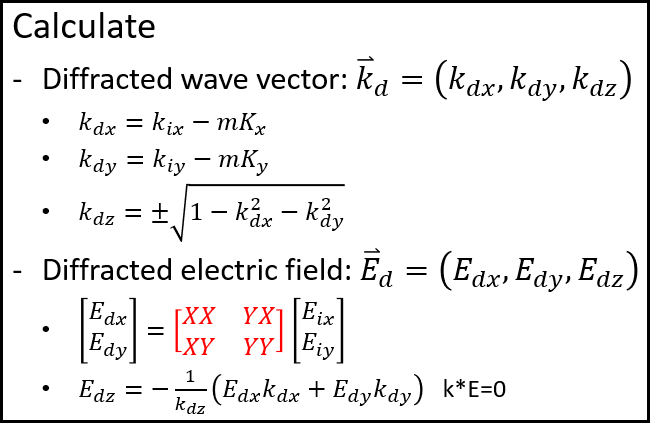
A: The change of polarization is completely considered and tracked during the simulation. Every ray in OpticStudio has electric field data (Ex, Ey, Ez), which updates everytime the ray interacts with objects, including the grating object we demonstrated in the webinar. Looking into more details, the calculation is like the following picture. The data we get from Lumerical is basically a 2x2 matrix that tells how to convert the incident (Ex, Ey) to diffracted (Ex,Ey).


Q: Does the number of analysis rays in Zemax matter when we want to export data and import to Lumerical?

A: In the topic of this webinar, we mainly export data from Lumerical and import it to Zemax. If you are exporting data from Zemax and import it into Lumerical, we will need to know what kind of data it is. However, not matter what data, I think # Analysis Rays will always be affecting. Usually the more the accurate and the slower you calcualte the data. If you can provide more details, I will be happy to answer more!


@mjean22 

Q: Is the dynamic link to Lumerical as fast or faster than using _rcwa.dll's included in previous OS releases?

A: Since in Lumerical RCWA, we use FFT to convert the geometry structure to Fourier space and other differences, it might be slightly slower than the built-in Zemax ***_rcwa.dll’s. However, this dynamic link provides some very nice feature that you cannot find with the built-in RCWA DLLs, as below.

  1. This support 2D gratings. The built-in Zemax RCWA DLL is optimized and especially designed for 1D gratings. This makes it neat and fast, but only works for 1D grating.
  2. You can easily customize your parametric model. Parameterization is very important when you wan to optimize and design your special grating shape. The Zemax RCWA DLL only supports limited choices of parametric 1D grating shapes.
  3. Lumerical FDTD UI allows you easily design your own grating with complicated shape. And it support import and export a lot of data format for the grating shape, such like .step and GDS II.

Q: Does the grating example work in sequential mode? (The example uses non-seq mode) / Can you share the files required to replicate the QR code example?

A: Currently this is only available in non-sequntial mode unfortunately. This is however possible to be implemented as a sequential surface. Please contact us with more details if you need this feature. It will also be very useful for us to know the requirement details for our future development plans.

We will share the file in a knowledge base article after this plugin is released in next release. Note this will be limited to only Ansys Zemax OpticStudio, Premium or Enterprise. If you are interested in getting a the beta tool earlier for your project, please contact support@zemax.com.


Q: How we can use ZEMAX in Laser cutting or in beam delivery? / How to import FTDT data in Zemax

A: I strongly suggest checking the following series of articles to know how you can simulate beam propagation in Zemax OpticStudio.

How to model laser beam propagation in OpticStudio: Part 1 - Gaussian beam theory and ray-based approach

How to model laser beam propagation in OpticStudio: Part 2 - Using Paraxial Gaussian Beam analysis to model Gaussian beam

How to model laser beam propagation in OpticStudio: Part 3 - Using Physical Optics Propagation to model Gaussian beams

For data transfer from Lumerical FDTD to Zemax OpticStudio, we also have a good article!

How to convert from Lumerical simulations to OpticStudio and back


Q: Can we model nonuniformities in the grating?  Say, varying pitch?

A: Unfortunately, we currently don’t support period varying as a function of position yet. We will appreciate if you can share more information how you need the period/pitch to be varied for our reference when we start to work on this.


Q: How do we combine 1D + 2D grating in real life? slide 24

A: The 1D and 2D gratings are at different regions on the waveguide, so we don’t really combine them. They are fabricated separately. I’m a little not sure if I answered this question, but please let us know if you have more questions!


@Fan.Chang 

Q: Is this diffractive dll built-in on zemax?

A: Yes, the dynamic link we demonstrated is based on a DLL plugin that will come together with Zmeax OpticStudio installation. This is not available yet, but you will be able to see it in next release. Note this DLL plugin links to Lumerical, which also needs another license to work.


Q: Could we get the MTF information?

A: Yes! Please find the following article where we introduced how you can simulate and calculate Huygens PSF/MTF.

How to simulate exit pupil expander (EPE) with diffractive optics for augmented reality (AR) system in OpticStudio: part 4


@Gokce.Toprak 

Q: Is phase data also saved within ray data in zemax?

A: Yes, every ray traced in Zemax OpticStudio includes a phase data that considers the accumulated optical path from the starting point to any point you check. By optical path, we mean the the product of the refractive index and the physical length.


@Yu.Wang

Q: can you share the example you walked through today? / If you can share the downlink for the ARwaveguide example will be great

A: We will release this tool soon in next release of OpticStudio. Note this will be limited to only Ansys Zemax OpticStudio, Premium or Enterprise. There will be a knowledge base article published with the example we demonstrated too. Please contact us (support@zemax.com) if you cannot wait and would like to play with the beta tool and example. Thank you!


@Yu.Wang

Q: can you share the example you walked through today? / If you can share the downlink for the ARwaveguide example will be great

A: We will release this tool soon in next release of OpticStudio. There will be a knowledge base article published with the example we demonstrated too. Please contact us (support@zemax.com) if you cannot wait and would like to play with the beta tool and example. Thank you!

Awesome! waiting for this. Also how can we be a part of expanding this feature to focus broadband source on to optomechanical waveguides. Can’t share much on this here, but that could be a revoloutionary idea. Would love to hear expert’s remarks on this!!


Q: In the third example of interface between Lumerical and Zemax, I understand how the amplitude and phase effects can be simulated in Zemax, but what about local changes in polarization?

A: The change of polarization is completely considered and tracked during the simulation. Every ray in OpticStudio has electric field data (Ex, Ey, Ez), which updates everytime the ray interacts with objects, including the grating object we demonstrated in the webinar. Looking into more details, the calculation is like the following picture. The data we get from Lumerical is basically a 2x2 matrix that tells how to convert the incident (Ex, Ey) to diffracted (Ex,Ey).


If I am not wrong, here we have used simple transfer matrix approach which works very well. Untill the radiations effects as per maxevillian theory (Einstein's Proposal of the Photon Concept—a Translation of the Annalen der Physik Paper of 1905: American Journal of Physics: Vol 33, No 5 (scitation.org) for longer wavelengths are considered. What would you like to say on my anticipation to have a method that could introduce moving boundary perturbations proportional to material density modulations can provide fruitful solutions? 


Q: How do we combine 1D + 2D grating in real life? slide 24

A: The 1D and 2D gratings are at different regions on the waveguide, so we don’t really combine them. They are fabricated separately. I’m a little not sure if I answered this question, but please let us know if you have more questions!

The only scenario that pops to mind after seeing this question could be to have them fabricated together on-chip for a broadband transmission case. However as answered above, unlike the designing part, simulating them simulataneously would be computationally challenging. Although it could serve a lot of applications.


@Yu.Wang

Q: can you share the example you walked through today? / If you can share the downlink for the ARwaveguide example will be great

A: We will release this tool soon in next release of OpticStudio. There will be a knowledge base article published with the example we demonstrated too. Please contact us (support@zemax.com) if you cannot wait and would like to play with the beta tool and example. Thank you!

Awesome! waiting for this. Also how can we be a part of expanding this feature to focus broadband source on to optomechanical waveguides. Can’t share much on this here, but that could be a revoloutionary idea. Would love to hear expert’s remarks on this!!

Hi Anurag,

Thank you for comments! This dynamic link itself just supports multiple wavelengths. You can simply create a light source with a given spectrum and simulate it. Just we need to be careful that too many sampled wavelength also means slow calculation because we don’t interpolate data  between wavelengths. Every new wavelength will trigger a new RCWA calculation.