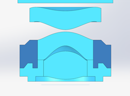
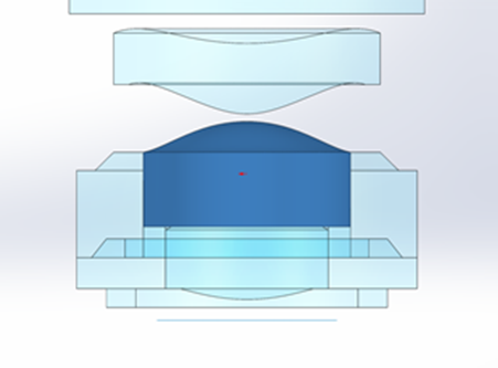
When designing cell phones and mobile LiDAR applications, or really any system with motion, vibration and shock can be a concern. One technique used by both cell phone and aero-space applications is to use step mounts on the optical elements to keep their motion more ridged. The issue with designing this type of step and testing the effects of FEA are how to integrate the optic with the step.
Today’s Tuesday Tech Tip is how to create a step mount and run a STOP analysis on the system. Creating these steps in a CAD platform and making the distance between the lens and the step a nominal size is the first step. Using a CAD tool that allows optical properties and ray tracing such as OpticsBuilder or Speos will help with this process. Next the FEA software needs to allow this nominal distance to be perceived as ideal for transferring forces and thermal effects. This will allow both thermal and structural data to run on the new combined optic of the lens and step as though it were a monolithic piece of glass. Once structural and thermal analysis has been run the data can be exported as a point cloud for use with STAR, part of Ansys OpticStudio Enterprise. This step is made easier in Ansys Mechanical by using the ACT script to automate exporting the data in a format STAR can import. Finally import the data into OpticStudio via STAR to perform the STOP analysis and compare the nominal system to the as simulated system using the same metrics and tools used to design the system.


Author: Steven LaCava / Senior Application Engineer
Article to Go Live on 9-13-22


