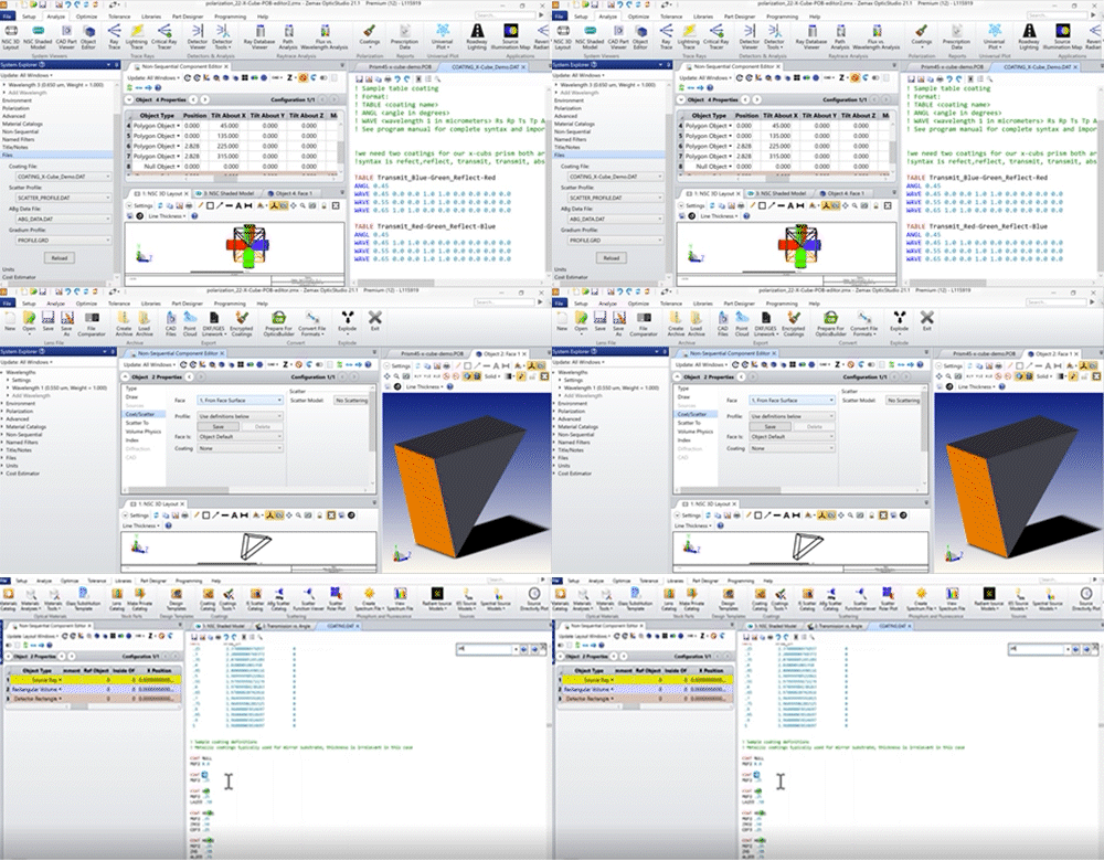
Thermal imagining consists of a pretty wide part of the spectrum containing three main groups with multiple sub-bands within each. So, what happens if we want a particular wavelength or want to filter all but a few select wavelengths, such as a specific sub-band of an IR-band? This is where coatings can help. Coatings in OpticStudio can be handled in a number of ways, off the shelf coatings can be used and called in the coat/scatter section under properties, encrypted coatings from vendors can be used allowing the optical simulation to be accurate while protecting the vendors formula of the coating. The Essential Macleod package can be used to design a coating and export a coating file that OpticStudio can read. Finally, my favorite method is to create your own coating as it offers the greatest control shown below, there are a few ways to do this and your custom coating can even be turned into an encrypted coating if you are working with outside contractors or joint venture projects where protecting your intellectual property is important.
To create a coating it can either be done as a series of layers of material types that are placed in stacks as thin films would be deposited. This is how you would create a coating for simulation that you wanted to have a formula to manufacture in the real world. This is useful in cases where you are designing your own coatings. Since most coating companies are very protective of what goes into the secret sauce, and few people design their own coatings, a more useful tool is often the simple or table syntax, where we focus on end optical result and not the chemistry that got us there. Many good coating houses can take this data and create a formula from it when it comes time to go to production.
For the simple or ideal coating syntax
COAT I.75 = transmits 75%, reflects 25%, absorbs 0%
Absorb2 0.95 0.03 = transmits 95%, reflects 3%, absorbs 2%
Note: if the values don’t add to 100% the remainder falls to the next term in the sequence
Table syntax gives a greater degree of control over how the coating performs as it can be defined for multiple angles of incident and a verity of wavelengths.
TABLE <coating name>
ANGL <angle in degrees>
WAVE <wavelength 1 in micrometers> Rs Rp Ts Tp Ars Arp Ats Atp
WAVE <wavelength 2 in micrometers> Rs Rp Ts Tp Ars Arp Ats Atp
WAVE <wavelength 3 in micrometers> Rs Rp Ts Tp Ars Arp Ats Atp
ANGL <next angle in degrees>
WAVE <wavelength 1 in micrometers> Rs Rp Ts Tp Ars Arp Ats Atp
WAVE <wavelength 2 in micrometers> Rs Rp Ts Tp Ars Arp Ats Atp
WAVE <wavelength 3 in micrometers> Rs Rp Ts Tp Ars Arp Ats Atp
Where: R is reflected intensity, T is transmitted intensity, Ar is intensity absorbed from reflection and At is intensity absorbed during transmission. The S&P subscripts on each variable denote the S&P directions, there by allowing polarization data to be incorporated.
Author: Steven LaCava / Senior Application Engineer


