
New surface equation for the Off-Axis Conic Freeform


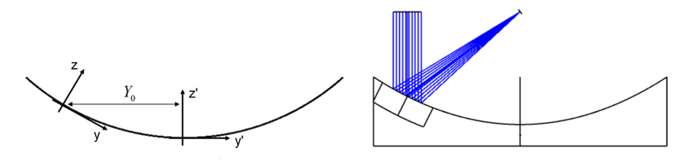
The Off-Axis Conic Freeform surface is the sum of an off-axis conic surface with freeform polynomial terms.  The coordinate system for the surface is decentered and tilted to the center of the off-axis conic, as shown by the (y, z) coordinate system sketched below.  Polynomial freeform terms are added to the surface at the center of the off-axis part.  The edges of a mirror defined by this surface shape are parallel to the z axis.


The sag of the surface can be written as:

where:

and R is the radius of curvature, k is the conic constant, Yo is the off-axis distance measured along the y axis of the on-axis conic, and Rn is the normalization radius for the freeform polynomial coefficients. The position coordinates x and y are in the off-axis coordinate system. 

The freeform polynomial allows 230 terms, up to y20.  The A00 term is omitted.  The coefficients are arranged by increasing total power (j+k) and then by decreasing powers of x^j, as shown in the equation below.  Note that the polynomial coefficients Aj,k are in lens units because the (x,y) coordinates are dimensionless.

The freeform coefficients are specified in the Lens Data Editor beginning with parameter 13.

More details on the Off-Axis Conic Freeform surface derivation and design examples can be found in D. Reshidko, J. Sasian, "A method for the design of unsymmetrical optical systems using freeform surfaces," Proc. SPIE 10590, International Optical Design Conference 2017, 105900V (27 November 2017). 

12 replies

Userlevel 4
Badge +1

Is there a direct conversion from a decentered aperture on an even asphere surface, to the off-axis conic freeform surface?

Userlevel 5
Badge +1

Hi, Sean.  No, the Off-axis Conic Freeform only allows for an underlying Conic surface shape.  And there is not an exact analytic conversion from an Off-axis Even Asphere to the Off-axis Conic Freeform, because the polynomial terms are tilted and decentered with respect to one another. 

That said, the polynomial freeform terms are fairly flexible, so you could try optimizing on the freeform terms to see if you can get close to the performance of your Off-axis Even Asphere. 

Or, you could possibly create a Composite surface stack to add the Even Asphere part of your surface to the Off-axis Conic Freeform….but I would have to mess with that a bit to see if it would work.  I think you could put the Even Asphere in front of the OACF, position it correctly, and turn on the Composite so that the two surfaces add.

Userlevel 4
Badge +1

Hi Erin, thanks for the reply. I know we spoke about this previously, so I was hoping with your new equation you had found the solution. I want to incorporate the off-axis conic freeform surfaces into my design, but will have to wait for a time when we are early enough in the process to try it out.

I think this surface type would help with visualizing clear apertures on off-axis mirrors, especially when looking at footprint diagrams. The help documentation is not very clear about which orientation you are viewing in the footprint diagram, and I wonder if the same off-axis coordinate flag available in the Sag analysis could be applied to a footprint diagram. 

Anyway, I’m going to try to convince my colleagues to try this surface out for future designs. Keep up the good work!

Userlevel 5
Badge +1

Hi, Sean.  Footprint diagrams and spot diagrams are always displayed in the YZ plane, according to the local coordinate system for the surface.  Apertures in sequential mode are the same, which means that some users define an elliptical aperture to get a circular substrate on an off-axis part. 

It is true that these problems are solved for the Off-axis Conic Freeform by having a local coordinate system that lies at the vertex of the part.

For other surfaces with vertices away from the off-axis aperture, I completely agree that allowing an off-axis coordinate system for apertures, footprint plots, and spot diagrams could be very beneficial.

I think you can use the Composite stack to solve your problem, actually.  Start with the off-axis conic freeform surface and just make it a sphere with the correct ROC and offset.  Then, add a Composite Even Asphere.  You can move the add-on surface so that the correct off-axis portion of it is added to the Off-axis Conic Freeform, using the position coordinates in the “Composite” property.  Result = a part that has the off-axis coordinate system that you’re looking for and a circular substrate.

Userlevel 4
Badge +1

I’ll have to try the composite stack method out. Thanks for the suggestion!

Userlevel 7
Badge +3

Hi Erin,

This is a really clever surface and one I wish we had decades ago. Well done to you and the team!

Just building on the final comments about the Composite surface...do you need this new surface, or can it all be done using the composite surface capability?

  • Mark 
Userlevel 5
Badge +1

Thanks, Mark!  Yes, it’s a really nice addition; I think Jose Sasian and Nick H. lobbied for it, initially.

If I had my way, we’d have an off-axis version of every surface shape in Zemax.  The advantage is the local coordinate system lying at the vertex of the off-axis part.  So the apertures are round, and it’s easy to add perturbations of any kind to the correct position, centered on the off-axis vertex of the surface.  This is a much better representation for any mirror larger than 4” diameter or so, where one would polish it directly into a substrate instead of cutting it out of a larger parent substrate.  

The Composite does lessen the pressure to add this off-axis form for every surface type.  One can’t move a surface’s coordinate system using the Composite stack, because it’s always taken from the Base surface in the stack.  But one can start with the Off-Axis Conic as the base surface, make it a sphere with K = 0, and then add any departures from the sphere using other surface types, as I suggested above for Sean’s case.  The Add-on surface can move around freely to get the correct tilt and decenter, so that the sags add correctly.  Really powerful stuff!


Userlevel 7
Badge +3

That’s super Erin, thank you

Userlevel 5
Badge +1

There’s an error in the sketch that I’m trying to fix:  the (x,y,z) coordinate system should be shown at the off-axis position, not at the parent vertex.

Userlevel 7
Badge +3

Hi Erin (@Erin.Elliott):

Thanks for posting about this new Off-Axis Conic Freeform surface. 

I took a look at Sasian’s paper that is referenced above (as well as in the help documentation).  The work is premised on the optical system being plane-symmetric, so for this reason they introduce the following polynomial for aberration correction:

It only has even powers of x.  However, the ZOS implementation uses a much more general extended polynomial (even though the help documentation seems to incorrectly refer to it as a plane-symmetric version):


So, my question is why do you guys implement a much more general version of the polynomial that is inconsistent with the symmetry of the original construction?  Maybe I’m missing something…  Do you happen to have an example of a system with less symmetry in which the additional coefficients prove beneficial?

Thanks,

Jeff

Userlevel 5
Badge +1

Hi, Jeff.  Yes, we did a complete rewrite of the Help file for our upcoming release, too.

We tend to use a fully generic polynomial for surface shapes because we don’t know what kind of perturbations folks will want to add to the mirror.  With all polynomial terms available, users can use pickups and such to mimic, say, a Zernike term that they care about.  (For example, 45-degree astigmatism is 2 (6^0.5) x y, which users could create by using the A1 and A2 coefficients to be equal, using a pickup on A2.)

The plane-symmetric aberrations have a different purpose.  The original U of AZ coefficients, Wijk, include the dependence on field angle, and made assumptions about rotational symmetry that aren’t as valid for an off-axis mirror.  The Wijkmn coefficients for plane symmetry are a more general set, and represent off-axis sections of the Wijk aberrations.  (These systems tend to be dominated by linear piston, unless one has satisfied the Sine condition.)  We hoped that some of the aberration terms would get into general use and earn names, like the 3rd order terms have, but no such luck so far.  LOL.

https://www.spiedigitallibrary.org/journals/optical-engineering/volume-41/issue-3/0000/Phase-theory-for-multiple-aperture-systems/10.1117/1.1431969.short
https://www.spiedigitallibrary.org/conference-proceedings-of-spie/4832/0000/Basic-principles-in-the-optical-design-of-imaging-multiple-aperature/10.1117/12.486468.short


Userlevel 7
Badge +3

Hi Erin,

Yes, I understand that the current implementation provides maximum flexibility, but sometimes less is more.  For example, I think it is fair to say that the even asphere surface is more useful than the complete asphere surface (with both even and odd power terms). 

With the introduction of the composite surface capability, the user can now add more complicated shapes (e.g., Zernikes) to a base surface, so the base surface itself need not support the more generalized sags.  That what makes the newer ISOX tolerance operands appealing. 

Regarding the Off-Axis Conic Freeform surface, all of the examples provided in the paper by Reshidko & Sasian use the plane-symmetric version of the polynomial.  Again, it would be interesting if someone could demonstrate, from a fundamental perspective, the benefit of the more general version of the polynomial as a base surface (and its much larger number of coefficients that need to be managed).

Regards,

Jeff

Reply