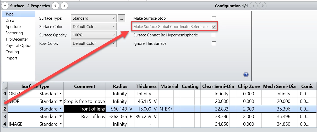
Hello there,
Let's say we have a very simple singlet system with two collimated fields which are focused onto an image plane. We now like to export this optical system, as a STEP format, from OpticStudio into our CAD environment. We can do so with the Export CAD File tool which can be found in the File tab of OpticStudio. Once the optical system is opened up in CAD (Here Ansys SpaceClaim) it looks like that:

As visible on the image of the exported Singlet above, the origin of the global coordinate system within the CAD environment is set at the beginning of the rays. This is because the first Surface was set as the Global Coordinate Reference in the Surface Properties of OpticStudio. To change the coordinate system origin point of the exported cad file, another surface can be set to be the Global Coordinate Reference surface.

Taking this Singlet as show case example, it can be observed that the origin of the global coordinate system has shifted from the beginning of the rays to the front surface of the lens:

Please feel free to ask any question which you might have about CAD Export!
Have a great day,


