Easily add measured data to any surface using the Composite property

  • 6 October 2023
  • 4 replies
  • 124 views

Userlevel 4
Badge +1

Measured interferometric data can be added to optical surfaces in OpticStudio using the Grid Sag surface.  We provide an automated method for converting .INT files into the .DAT format used by the Grid Sag in the File/Convert File Formats tab, as shown below.  This method works well when the optical surface being measured is a Standard or Even Asphere shape.  

For other surface shapes, it was necessary to convert to a Grid Phase surface (which can cause XY position errors) or to place the underlying optical surface shape into the sampled data (which converts an analytic surface to a sampled one, for a loss of precision and speed during raytracing).  Both methods also require data manipulation outside of OpticStudio.

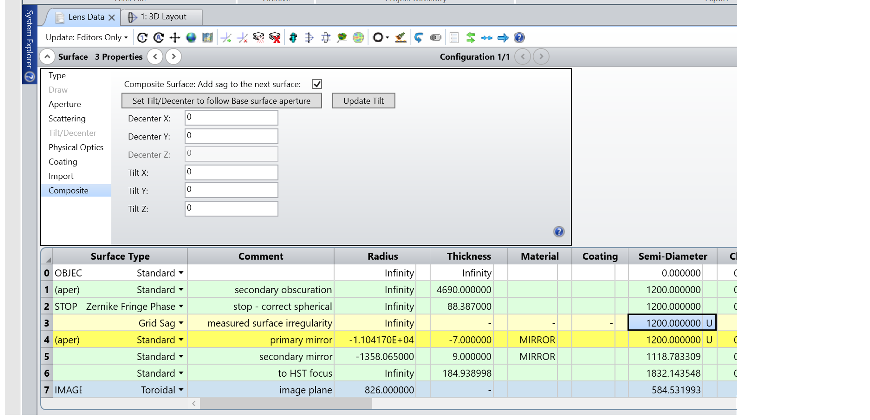
With the new Composite surface capability, interferometric data can be easily added to any surface shape, and the accuracy and speed of raytracing is preserved.  Users can convert the data from .INT to .DAT as before, and then place a Grid Sag surface before the optical surface in the Lens Data Editor, as shown below.  Then, turning on the "Composite" property adds the Grid Sag to the next surface, as shown below for the primary mirror of the Hubble Space Telescope.  Now the measured data is added to the mirror surface, and the total sag is contained in surface 4.  (The raytraces no longer interact with surface 3; just with the combined total sag in surface 4.)

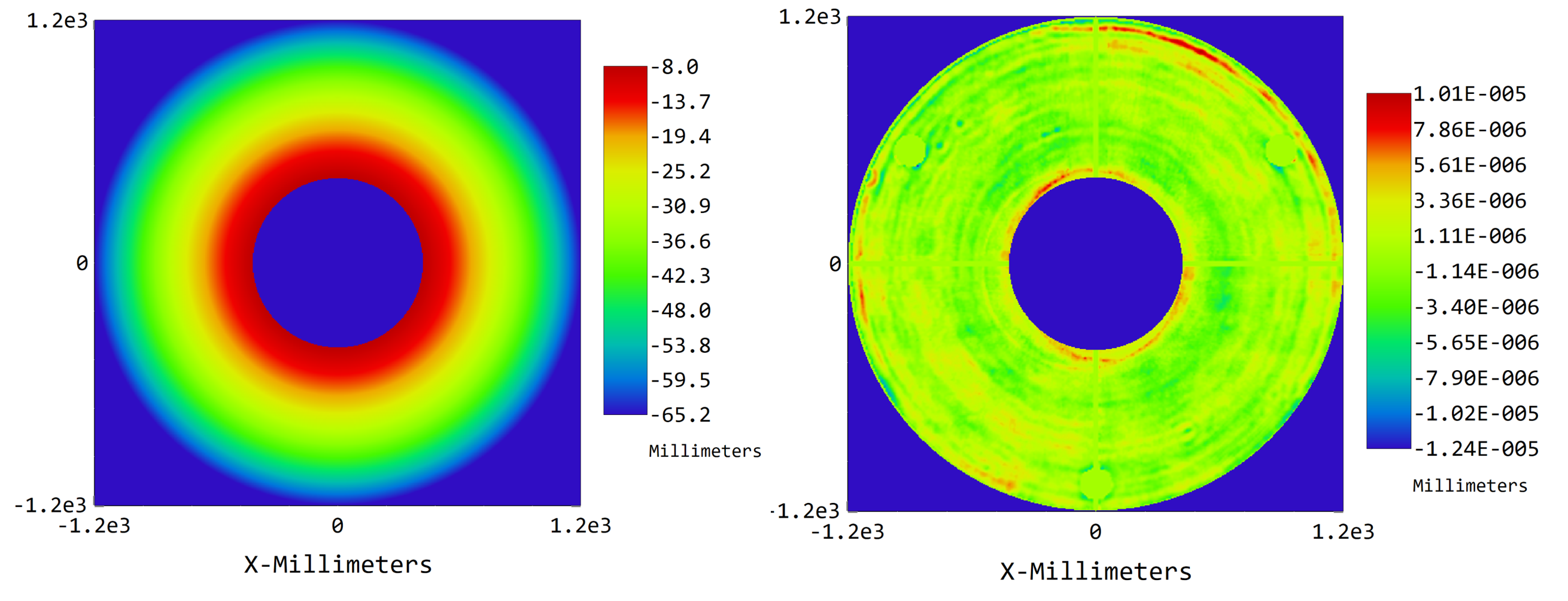
The sag map for the primary mirror can be seen by using Analyze/Surface/Sag Map.  The sag is dominated by the ROC of the mirror, as shown below.  But the interferometric data alone can be plotted by choosing Base Sag in the Remove option of the Sag Map’s settings.  (The measured data shown is approximate.)


4 replies

Userlevel 7
Badge +3

This is excellent. It’s a huge step forward in simplifying one of the most frequently-asked-questions, or frequently stumbled upon problems, in optical engineering. This feature, along with HYLD, are real 21st century contributions to optical design.

  • Mark
Userlevel 3
Badge

 @Erin.Elliott, Thank you for the great example.

What was the resolution of the grid sag data? Can you share the example data? I’d like to experiment with it to see the effect on speed.

I’m also curious what is the purpose of surface 2?

Thanks again,

John

Userlevel 4
Badge +1

Hi John.  I knew someone was going to ask for the files, because I didn’t convert them to true sag values; the attached are the files with all the data in terms of phase, so will need to be converted by (wvl / (2 * 2pi)) before using as sag with the Composite stack. 

You’ll see that the data isn’t high in spatial resolution; Hubble went up in 1990, remember, so interferometers struggled even to have 256x256 detector pixels.

Surface 2 is a correction for the spherical aberration that was accidentally built into the Hubble primary.!  That was corrected by COSTAR during the first servicing mission.  Later, most Hubble instruments skipped COSTAR and just put the correction into their own designs.  We were lucky, in a way, because spherical aberration is constant across the FOV and easy to correct for.

Userlevel 3
Badge

Hello @Erin.Elliott,


Thanks for sending the data and archive file. I’m now realizing this is actual data from Hubble Space Telescope, so cool!


As you suggested, I’ve scaled the .dat files and used them as composite grid sag surfaces. The model still updates fast and simple optimizations finish quickly.


FYI, the direction of the secondary error shows up in the opposite direction as compared to the grid phase surface in your file. I’m not sure which is correct.


I did notice that .INT file headers have a comment “A value of 10,000 = 1 um of error.” Does this suggest this is sag data? In this case, I see the OS native conversion tool will create a grid sag if you change “WFR” to “SUR” in the .INT header. However, this scales the error by 2/(lambda in microns) which seems like more error than would have been tolerated for space telescope optics…


Thanks for the background on the HST spherical aberration. I read through the ‘failure report’ and found it quite interesting.

Reply