The attached are two files that shows how to simulate CMOS diffraction using the static link in OpticStudio.
More information about using static link can be found in the following article:
How to load grating data from Lumerical into OpticStudio – Ansys Optics
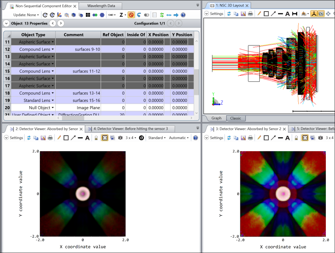
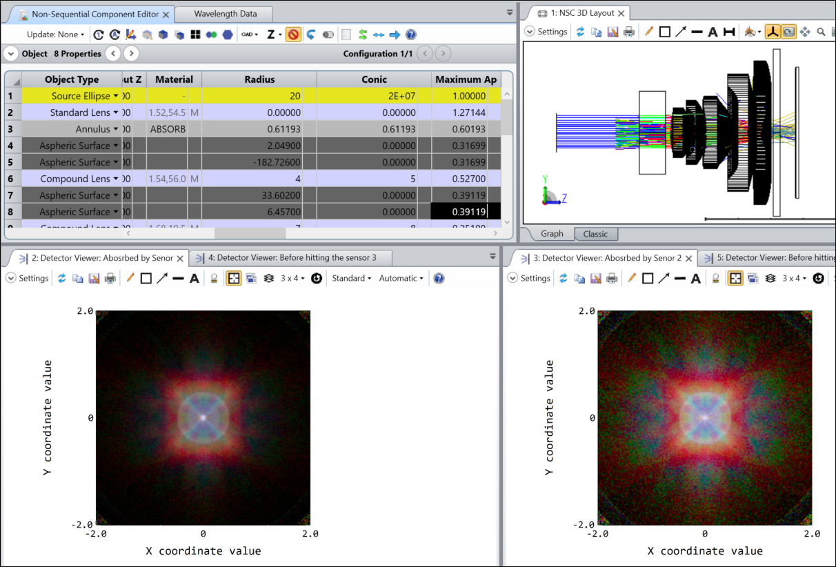
When the files are opened, it might look as below.
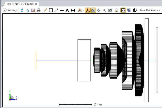
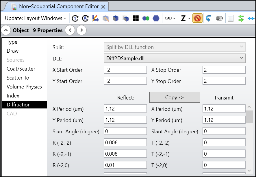
It’s not difficult to find object 21 is set up with the static link, which is supposed to simulate how CMOS can diffract lights and cause straylight when it comes back.
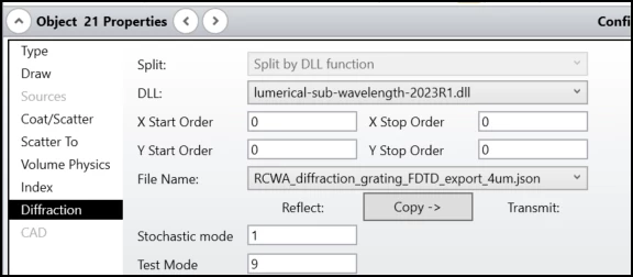
The Stochastic mode is turn on because rays will revisit the CMOS many times and generate so many calculations.
The Test Mode is set to 9 for a special handling to the grating data. Normally, when light hits CMOS, most of the power is absorbed and converted to electric power in the pixels. And only a certain ratio of power is diffracted in the reflection direction. If the grating data is generated from Lumerical, there will be only reflection diffraction and no any transmission order. The trick of Test Mode = 9 is it calculates total reflection diffraction power in R and put all the (1-R) power to the transmission order (0,0). In this way, we can easily check the absorbed power by placing a detector after the grating.
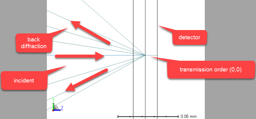
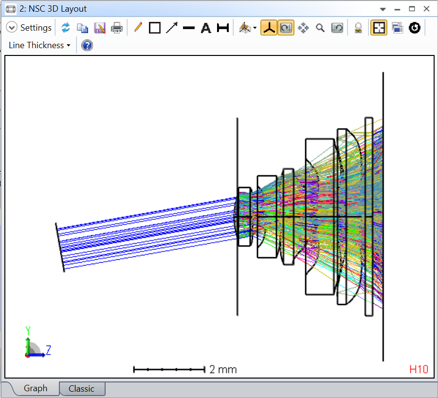
By setting a larger Layout Rays #, we can observe how the system looks like.

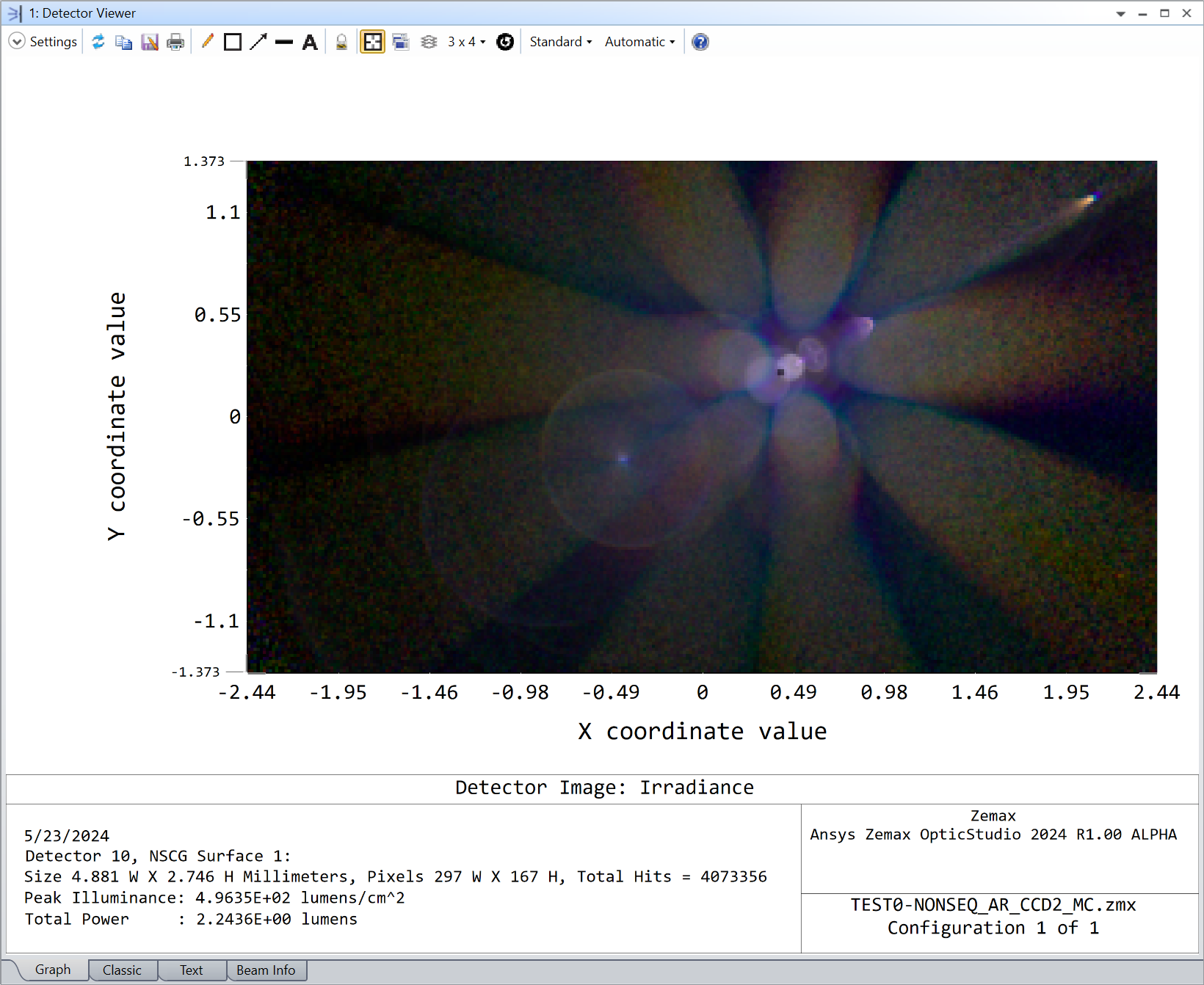
And the simulation results are as below for 1 um and 4 um CMOS.
