Released: January 21st, 2020
1 Sequential Tools, Features, and Capabilities
1.1 Tolerance Presets from Industry (All Editions)
Set up accurate tolerances in one click, using vendor submitted tolerance presets
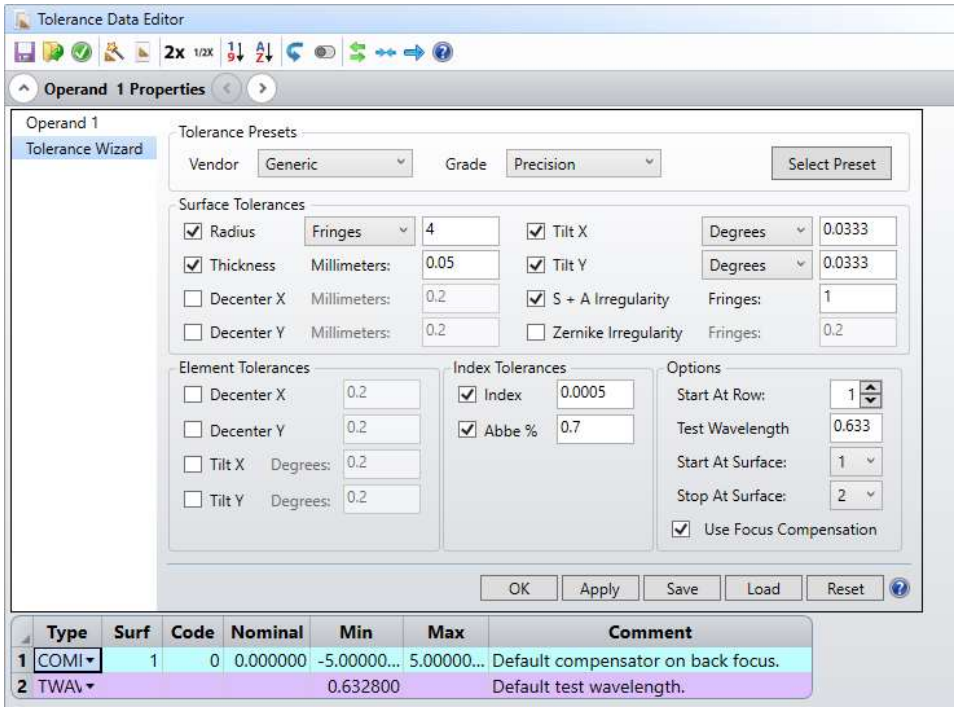
OpticStudio 20.1 now features tolerance presets from Asphericon, Edmund Optics, LaCroix Optics, and Optimax in the Tolerance Wizard. This allows users to instantly set up the tolerance data editor with realistic values from their preferred vendor. The new tolerance wizard is shown in Figure 1.1.a.
1.2 QUICK SENSITIVITY (ALL EDITIONS)
An all new method to get fast approximate insights into the system’s most sensitive parts
Quick Sensitivity is a new tool that runs a fast, approximate, sensitivity analysis giving the user an indication of whether they’re heading in the right or wrong direction. Unlike the full tolerancing capability, Quick Sensitivity only has 4 options on one page and is optimized to give quick results. The fast response, typically seconds, allows the user to check frequently during the design process, giving continuous insight into the direction of the design. The Quick Sensitivity tool can be found in the Tolerance Tab > Quick Sensitivity as seen in Figure 1.2.a.
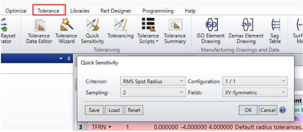
Please note that this tool provides a sensitivity-only analysis with Paraxial Focus compensation. In addition, any element tolerances in the Tolerance Data Editor (TEDX/TEDY/TETX/TETY) will be ignored. For a complete, rigorous analysis of all tolerance sensitivities, use the full Tolerancing tool.
1.3 SLOPE ANALYSES & OPERAND (ALL EDITIONS)
A new Surface Slope analysis and accompanying operand help constrain freeform surfaces for improved manufacturability
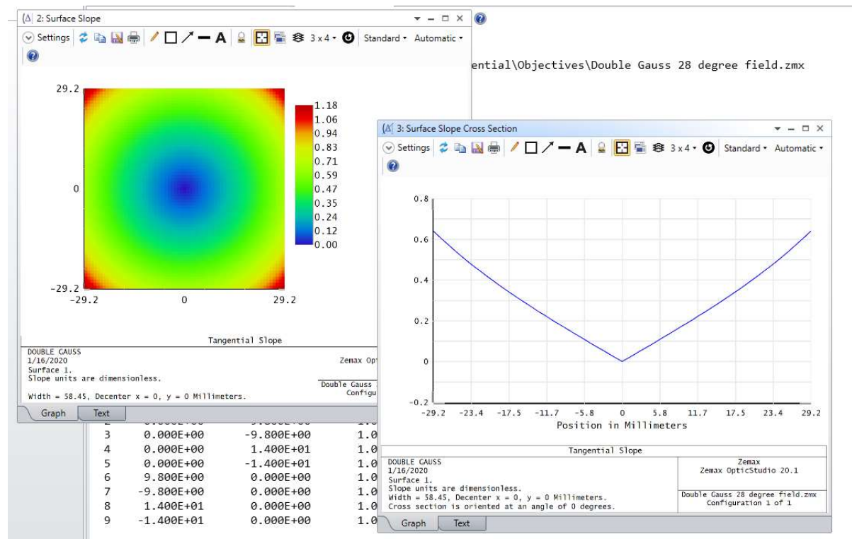
To better support modern manufacturing processes and constraints, OpticStudio 20.1 has added a new Surface Slope analysis, as well as an accompanying operand, SSLP. This analysis functions similarly to the Curvature analysis with the ability to look at Tangential, Sagittal, X, and Y slope of any surface. The Slope Analyses can be found in the Analyze Tab > Surface > Surface Slope, and the Analyze Tab > Surface > Surface Slope Cross Section. These analyses are shown in Figure 1.3.a.
1.4 OFF-AXIS SUPPORT FOR SURFACE DATA ANALYSES (ALL EDITIONS)
All surface data analyses now have improved support for off-axis systems
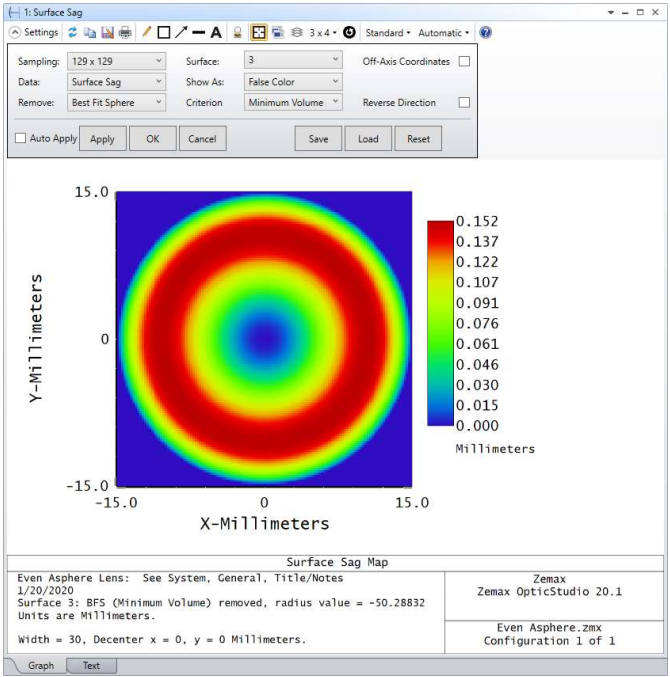
The Sag, Sag Cross Section, Curvature, Curvature Cross Section, Phase, Phase Cross Section, Slope and Slope Cross Section analyses all have an added checkbox “Use off-axis coordinate system”. When this is checked, the plot will consider any apertures defined in the Surface Properties of the surface. The coordinate system for the data computation will have an origin at the vertex of the off-axis part. Valid apertures for this option will be: Circular Aperture, Rectangular Aperture, Elliptical Aperture, User Aperture, and Floating Aperture.
The Sag, Curvature, and Slope analyses also have the ability to remove the base radius and the best fit sphere from the plot, while the Phase analyses have the ability to remove piston, tilt, and power. The new checkbox and remove options can be seen below in Figure 1.4.a.
1.5 TRUEFREEFORM SURFACE (PREMIUM EDITION, SUBSCRIPTION ONLY)
Cutting edge freeform technology, utilizing grid point optimization
The TrueFreeForm surface type defines a freeform surface as a grid of sag points on top of a combination of Biconic terms, Even Asphere terms, Extended Polynomial terms, and Zernike Standard Sag terms. This surface type will allow users to add any of these terms to an already defined surface (via the conversion tool “Make TrueFreeForm”) and optimize specific sections in the grid of sag points via the Grid Point Selector tool. TrueFreeForm
 enables the creation of surfaces which were previously not possible using only a parametrized surface. In Figure 1.5.a a TrueFreeForm
 surface is used to design an eye tracking system for an XR application.
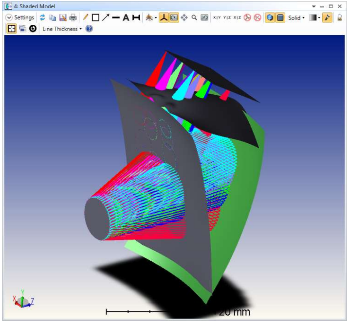
 surface being used in an XR application
1.6 GRID POINT SELECTOR TOOL (PREMIUM EDITION, SUBSCRIPTION ONLY)
Easily specify regions of interest for optimization on the TrueFreeForm™ surface
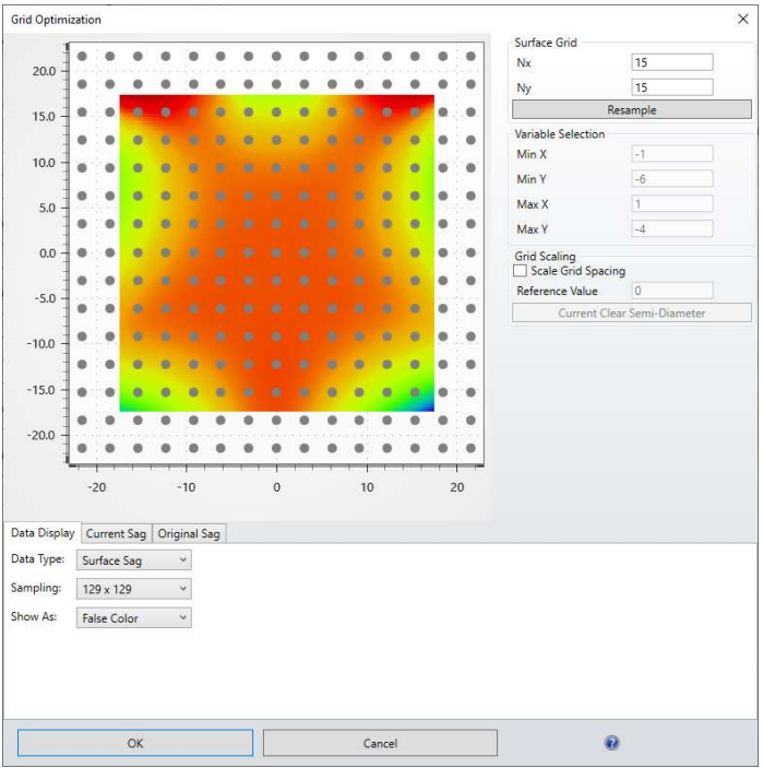
The Grid Point Selector tool displays the grid of sag points defining the TrueFreeForm surface. The Grid Point Selector tool allows access to and manipulation of the TrueFreeForm
 sag grid, without the need to interact with an external text file of sag data. In the display area, the sag points are displayed as grey dots. Overlaid on this grid, surface sag data or ray footprint data can also be displayed as seen in Figure 1.6.a. Additionally, this tool can be used to resample or scale the sag grid. The Grid Point Selector tool can be found in the Lens Data Editor toolbar.
1.7 MAKE TRUEFREEFORM TOOL (PREMIUM EDITION, SUBSCRIPTION ONLY)
Convert any surface into a TrueFreeForm™ surface
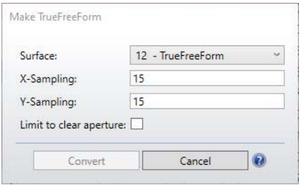
Make TrueFreeForm converts an existing surface to a TrueFreeForm
 surface type while conserving any standard, aspheric, polynomial, biconic, or Zernike parametric terms. A grid of sag points is placed on top of the parametric base shape for these surfaces. Supported surfaces without full parametric support are instead sampled as a grid of sag points during conversion. The Make TrueFreeForm
 tool can be found in the Lens Data Editor and is shown in Figure 1.7.a.
1.8 EXPORT TO POINT CLOUD TOOL (PREMIUM EDITION, SUBSCRIPTION ONLY)
Export any sag surface to a point cloud
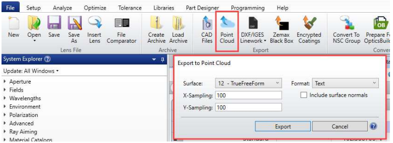
Export to Point Cloud exports the selected sag surface to a point cloud in the PCD format. This tool can be found in the File Tab > Point Cloud as seen in Figure 1.8.a.
1.9 ZERNIKE CALCULATION SPEED IMPROVEMENT (ALL EDITIONS)
Zernike based calculations are now 3x faster and 1000x more accurate
By utilizing a new Zernike calculation method (1), OpticStudio’s Zernike calculations are now 3x faster and 1000x more accurate. This improvement applies for all Zernike based calculations including Zernike surfaces and optimization.
1.10 SURFACE DATA OPERANDS UPDATES AND ADDITIONS (ALL EDITIONS)
Surface data operands have been added and updated to reflect the new improvements to the surface data analyses
SSAG has been updated to reflect the new settings in the Surface Sag analysis and SCRV, SPHS, SSLP, DSAG, DCRV, DPHS, DSLP have all been added to reflect the new available data.
SSAG, SCRV, and SSLP report the sag, curvature, or slope, respectively, in addition to having options for off-axis coordinates, removal of the base radius, and removal of the best fit sphere.
SPHS reports the phase and has options to remove the piston, tilt, and power.
DSAG, DCRV, DSLP report data about the surface including the Mean, PV, Minimum, or Maximum data value across a specified surface as well as the X or Y coordinates of Min data value, or the X or Y coordinates of the Max data value. This operand has data, sampling, off-axis, remove, best-fit sphere (BFS), and Orientation flags. DPHS reports the phase data of the surface. Phase data includes the RMS, PV, Minimum, or Maximum phase value across a specified surface as well as the X or Y coordinates of Min phase value, or the X or Y coordinates of the Max phase value. This operand has data, sampling, and remove flags.
1.11 NEW DLL: US_ZERNIKE+MSF.DLL (PREMIUM EDITION, SUBSCRIPTION ONLY)
A new User Defined Surface which models mid spatial frequency
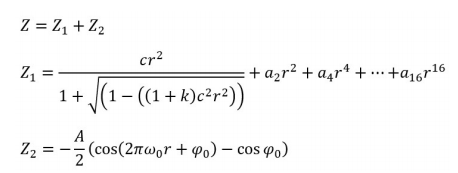
The us_zernike+msf.dll User Defined Surface models a Zernike Standard Sag surface with an additional ripple term. The even aspheric part of this surface is as described in Figure 1.11.a.
1.12 NEW DLL: US_HOLOGRAM_KOGELNIK.DLL (PREMIUM EDITION, SUBSCRIPTION ONLY)
Model diffraction efficiency in volume holograms using the new User Defined Surface (SEQ)
This DLL models a volume hologram, also called Volume Bragg Grating, based on the Kogelnik2 method. Its construction system is defined in a way similar to surface types Hologram 1 and Hologram 2. More parameters, such as the hologram's average index, modulation index, and Thickness, are used to calculate the diffraction efficiency. Tolerance parameters, such as Shrinkage and Index shift, are included for manufacturability analysis. See Knowledgebase article "Simulating diffraction efficiency of a volume holographic grating using Kogelnik’s method" for more details about how to use this DLL.
1.13 NEW DLL: HOLOGRAM_KOGELNIK.DLL (PREMIUM EDITION, SUBSCRIPTION ONLY)
Model diffraction efficiency in volume holograms using the new User Defined Diffraction (NSC)
This is the non-sequential model of the previous DLL.
1.14 NEW DLL: SRG_TRAPEZOID_RCWA.DLL (PREMIUM EDITION, SUBSCRIPTION ONLY)
Model trapezoid gratings with diffraction efficiency using this DLL
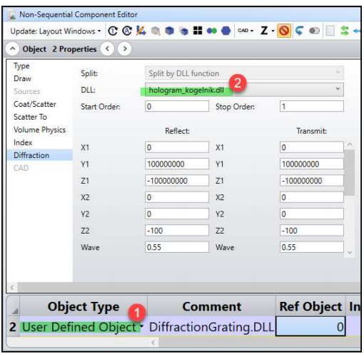
Using this new diffractive DLL, trapezoid gratings can now be modelled with accurate calculation of diffraction efficiency. This DLL can be used in non-sequential mode in the Diffraction Object Properties of the User Defined Object, Diffraction Grating as seen in Figure 1.14.a. More information about this functionality can be found in the Knowledgebase article “Simulating diffraction efficiency of surface-relief grating using the RCWA method”.
1.15 NEW DLL: SRG_STEP_RCWA.DLL (PREMIUM EDITION, SUBSCRIPTION ONLY)
Distortion can now be controlled in the Default Merit Function
This DLL is a variation of the previous DLL. Using this new diffractive DLL, step surface relief gratings can now be modelled with accurate calculation of diffraction efficiency. This DLL can be used in nonsequential mode in the Diffraction Object Properties of the User Defined Object, Diffraction Grating as seen in Figure 1.14.a. More information about this functionality can be found in the Knowledgebase article “Simulating diffraction efficiency of surface-relief grating using the RCWA method”.
1.16 NEW USER ANALYSIS: PHASE PLOT FOR BINARY 2 SURFACE (PROFESSIONAL & PREMIUM EDITIONS)
Analyze the phase of a Binary 2 surface with this user analysis
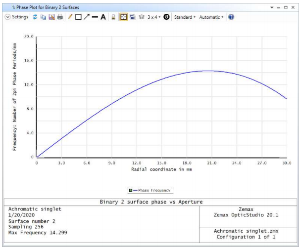
This user analysis creates a graph showing the phase and the inverse of the phase slope for Binary 2 surfaces. The plot indicates the phase over the clear semi-diameter or semi-diameter of the surface. This graph has identical functionality to the deprecated DDE extension, PhasePlot. The frequency of a binary 2 surface can be seen in Figure 1.16.a.
1.17 NEW OPERAND: EFLA, EFFECTIVE FOCAL LENGTH IN AIR (ALL EDITIONS)
Calculate the In-Air EFL of any lens
EFLA calculates the effective focal length in air in lens units. This is calculated from the surface defined by the parameter Surf to the next. The wavelength used is defined by the parameter Wave.
2 Programming
2.1 NEW ZOS-API EXAMPLE: NCE DETECTOR DATA (PROFESSIONAL AND PREMIUM EDITIONS)
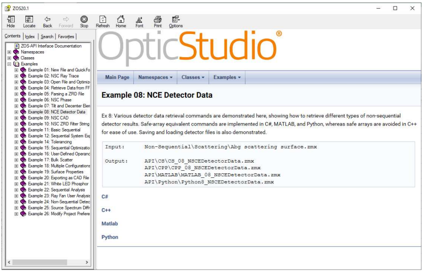
A new example showing how to retrieve NSC detector data using the ZOS-API
Retrieving non-sequential detector results using the API is simpler than ever with the new built-in example in the ZOS-API Syntax Help. The new example is “Example 08: NCE Detector Data” as seen in Figure 2.2.a.
3 Usability
3.1 PREPARE FOR OPTICSBUILDER (PROFESSIONAL AND PREMIUM EDITIONS)
Seamless handoff to opto-mechanical engineers
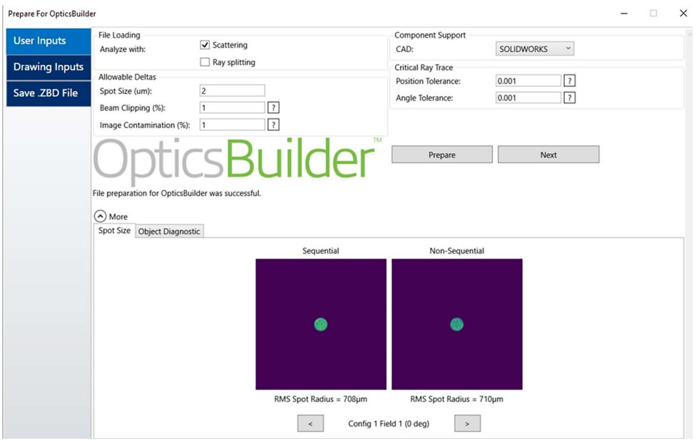
The Prepare for OpticsBuilder tool converts an optical system in OpticStudio to a CAD-friendly .ZBD file, ready to be used in OpticsBuilder. Prepare for OpticsBuilder tests the conversion output to ensure the OpticsBuilder user has a valid, usable file. If Prepare for OpticsBuilder discovers an error during conversation, it will deliver an error message to help resolve the issue. More information on Prepare for OpticsBuilder and converting from sequential to non-sequential mode can be found in the Knowledgebase Article “Prepare for OpticsBuilder”.
3.2 OPEN ZBD FILES (PROFESSIONAL AND PREMIUM EDITIONS)
ZBD Files can now be opened in OpticStudio
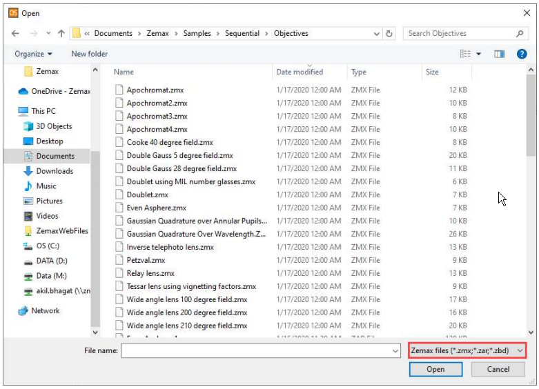
After a ZBD file is created from the Prepare for OpticsBuilder tool, it can be opened in OpticStudio as well as OpticsBuilder. Additionally, ZBD files created in OpticsBuilder can be opened in OpticStudio.
4 Libraries and Catalogs
4.1 CATALOG UPDATES (ALL EDITIONS)
Get the latest catalogs from Auer Lighting, NHG, Nikon, Nikon-Hikari and Edmund Optics.
Material Catalogs
- The AUER-LIGHTING Materials Catalog has been added. This catalog contains the material SUPRAX 8488, which is a borosilicate glass with high thermal and chemical resistance.
- The NHG Materials Catalog has been updated to include several new materials: H-FK95, H-ZK20, D-K9, D-ZK50, D-PK60, D-ZLaF52L, D-ZLaF52N-M170, and LaF5. The data of refractive indices in near-infrared band (852.11nm, 1013.98nm, 1064.00nm, 1128.64nm, 1529.58nm, 1970.09nm, 2325.42nm) and temperature coefficients of refractive indices dn/dt from -60°C to 160°C are improved. The thermal expansion coefficients of every 10°C from -50°C to 160°C and solarization △λ are added. The stress photoelastic coefficient B is also updated.
- The NIKON Materials Catalog has been made obsolete, which is reflected in the catalog comment. Only the NIKON-HIKARI Materials Catalog will be updated in the future, NIKON.AGF will be kept for past design files only
- The NIKON-HIKARI Materials Catalog has been updated to include changes to hightransmittance glass types in the high-refraction region: J-SFH1HS, J-LASFH15HS, and JLASF015HS. An improved version of Q-PSKH52S, an optical glass for molded lenses, has been released. Transmittance data for all glass types has been updated. Thermal property data has been updated for J-BAF12 and J-SK16. For the NIFS and NICF series, thickness data in internal transmission has been fixed from 1.0mm to 10.0mm.
Stock Lens Catalogs
- The Edmund Optics Stock Lens Catalog has been updated to remove a cement layer in certain doublet lenses as the cement material is not included in the Materials Catalog.
5 Performance and Stability Improvements
OpticStudio 20.1 includes the following feature improvements:
Sequential tools and features
- Spot Diagram – The axis and label placements now work correctly for different aspect ratios and graphics resolutions.
- Relative Illumination – Added a warning when the assumption that “the object scene is a plane” is not satisfied.
- Active Overlay – Active overlay now works when one of the analyses is on the text tab.
- Zemax License Manager – Added sorting to the “Activated” and “Total/Available” columns.
- Optimization - Stability improvements when terminating an optimization early and using IMSF operand to change the image surface in the Merit Function.
Programming
- Full Field Aberration is now supported by the ZOS-API and ZPL – ZOS-API and ZPL functionality has been added to support the Full Field Aberration analysis.
6 Bug Fixes
OpticStudio 20.1 includes the following bug fixes:
Sequential tools and features
- Merit Function Editor – The IMAE operand now works correctly with the CONF operand.
- User Defined Surface – The ‘did_polar’ flag for a User Defined Surface (UDS) now correctly passes the S/P polarization values for ‘did_polar = 1’; or the E-fields for ‘did_polar=2’; for use with the CODA Merit Function operand and the Polarization Ray Trace analysis. Previously the ‘did polar’ flag was ignored by CODA and the surface treated as uncoated.
- DDE Compatibility – Fixed an issue where a user could not run the DDE and/or use the Command Line Interface tool when using a Subscription license.
- License Compatibility – Black keys issues before 2016 now correctly function with the Material Substitute Solve and the ZPL.
- Sag Table – Updates to the Best Fit Sphere (BFS) and Maximum Slope Deviation algorithms in the Sag Table and related analysis. Cases which incorrectly reported a BFS smaller than the lens’ semi-diameter, where the Sag Table’s maximum radius exceeds the lens’ semi-diameter, the concavity changes but the sag remains constant, and the semi-diameter approaches the radius of curvature (hyper-hemispheric condition) have all been improved to return consistent results with the correct minimum RMS deviation.
- Field Data Editor – Pickup solves can now be edited after they are originally set.
- Polarization Ray Trace – The relative transmission calculation is no longer greater than 1 when a real propagation is followed by a virtual propagation.
Programming
- Vignetted Rays – In the ZOS-API, the DataGrid() for the IAR_ for both the Interferogram & PowerPupilMapSettings analysis now reports NaN (rather than 1.0) for vignetted (x, y) points outside the pupil; note that the actual calculated data has not changed and was not affected by the vignetted rays.
- Tolerancing – In the ZOS-API, the OpenTolerancing() tool under the IOpticalSystemTools interface now opens the tool without immediately running a tolerance.
- Field Data Editor – The ZOS-API command MakeEqualAreaFields(numFields, maxField) now properly adds the number of fields for field values between 0 to the maximum field value.
- Grid Data – The ZOS-API method SetData() under the IUserGridData & IUserGridRGBData interfaces was not properly drawing a 2D grid in a User Analysis.
(1) Andersen, Torben. (2018). Efficient and robust recurrence relations for the Zernike circle polynomials and their derivatives in Cartesian coordinates. Optics Express. 26. 18878. 10.1364/OE.26.018878.


