


May 31, 2022
1 Sample Files
In OpticsBuilder for Creo 22.2 we have added a new sample file:
- Spectrometer
2 Training
The OpticsBuilder OpticsAcademy course is now available!
Access guided training online and on-demand for OpticsBuilder through the OpticsAcademy. This training is perfect for new users or users looking to sharpen their skills using OpticsBuilder. Find Individual Courses under the Training tab on Zemax.com. Currently available in English only. Pricing to be determined.
3 Tools, Features, and Capabilities
3.1 Advanced Ray Geometry Tools - Chief Rays
Interactive Chief Rays now perform a separate Simulation
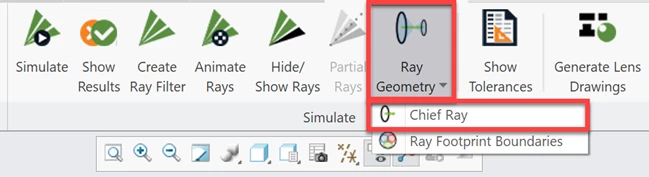
In OpticsBuilder for Creo 22.1 we introduced the Chief Ray tool. A ray trace is needed to generate the chief ray(s) for the system and this additional ray trace was added onto the general Simulation function. In 22.2 we have now separated the additional ray trace for the Chief Ray so as not to add additional time for users that do not choose to use this new tool. To generate the Chief Ray, users need only to select the Chief Ray from the Ray Geometry drop-down.
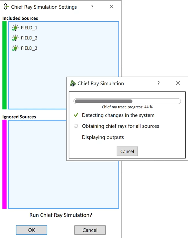
Users will then choose which sources they wish to generate a Chief Ray from, and a Simulation will run upon selecting “OK”.
*Please note that coming in 22.2.1 we will allow a setting to automatically start the additional Simulations for Chief Ray and Ray Footprints after the general Simulation is run. This will allow users that are actively running all Simulations during iteration to choose to run them automatically together.
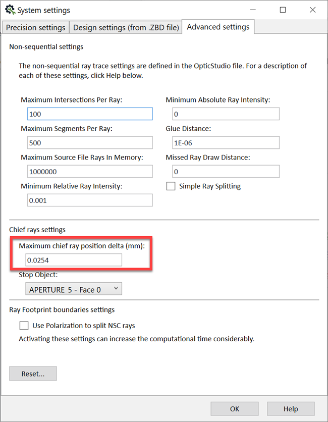
Chief Ray delta now shoes unit of measurement
The Chief Ray tool also includes settings found in System Settings > Advanced Settings. This is where users may see and/or select their stop object and where they may set the maximum position delta of the chief ray(s). We have now added the unit of measurement to this area (millimeters) to ensure that CAD users specify their allowable delta for the chief ray(s) position accurately.
3.2 Advanced Ray Geometry Tools - Ray Footprint Boundaries
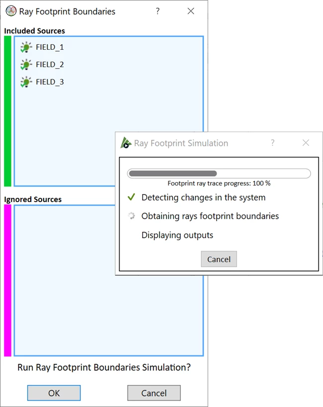
Interactive Ray Footprint Boundaries allow CAD users to design better optical products
In OpticsBuilder for Creo 22.2 we introduce the new Ray Footprint Boundaries tool. The Ray Footprint Boundaries tool generates ray footprint boundaries on the lens surfaces based on the source(s) you select during the setup. CAD users can click on these boundaries and utilize their CAD tools to measure, position, and analyze the effects their mechanical components have on the ray set. This will help users to make informed decisions and further changes to their mechanical assembly within the CAD environment and ensure that their assembly is meeting the requirements as defined by the ray path.
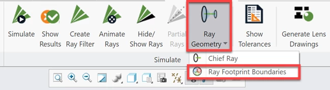
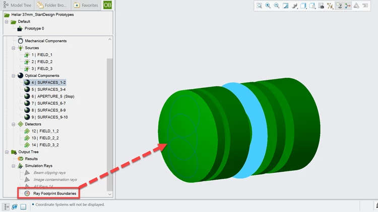
A separate Simulation will run to generate the Ray Footprint Boundaries.
4 Bug Fixes
OpticsBuilder for Creo 22.2 includes the following bug fixes:
- Mirror with a hole does not display correctly – Optical products designed with a mirror containing a hole were experiencing issues when loading their file into PTC Creo using OpticsBuilder. Since mirrors with holes are considered a Boolean object, it would load into OpticsBuilder as a STEP object and this geometry displayed in PTC Creo as a hollowed object, without front and rear surfaces. We are working with PTC Creo on a permanent fix for this issue but in the meantime, we have changed this mirror with a hole object to load into OpticsBuilder using IGES instead of STEP. This allows users to display the geometry correctly within PTC Creo.
- Chief Rays not updating with mechanical change – If a mechanical component changed position or was removed from the Region of Interest in OpticsBuilder, a user would then need to run a new Simulation to get updated results. This bug was not updating the generated Chief Rays in this scenario but has now been fixed.
- Layout /Analysis Rays trigger modified system Results – If a user right-clicked on a source in the Optics Manager and chose to change the number of Layout Rays or number of Analysis Rays, it would change the designation of the system to a “modified system”. After running a Simulation, the Results window would display the results for a “modified system” instead of viewing this as the “original system” and offering Results compared to the OpticStudio baseline.
- Rays Ignore Object designation triggers modified system Results – When a user right clicks on an optical component and opens its’ properties, they may choose to change the designation “Rays Ignore Object” for the Simulation. This setting would then trigger the Simulation and Results window to view the system as a “modified system”. This setting should not trigger a designation change to the system and should instead only show the Results to the “original system” compared to the OpticStudio baseline.
- Add Source/Detector properties – If a user clicked on the Add Source/Detector tool, it defaults to add a source. If the user then clicked on the “Preview” button and then changed the component type from “source” to “detector”, the properties of the detector were not available.
- Generate Lens Drawing tool – Additional cemented component part and assembly drawings were being generated for a non-cemented component.
- Color rays by source UI – When the “color rays by source” option was enabled in the Simulation settings, the Beam Clipping and Image Contamination rays were not changing color in the graphics area.
- Optomechanical component Reference Geometry – When changes are made to an optical component using CAD tools (such as adding a chamfer to an optical edge), it changes its designation to an optomechanical component. When this designation change occurred, the Reference Geometry for the component was not longer available. We have fixed this so that Reference Geometry is still available on these modified optomechanical components.
- Update .ZBD file – If a user applies a ray filter to the Simulation and then chooses Update .ZBD file, the previous ray filters remained on the Simulation instead of resetting the Simulation to the default settings.
- Optical tolerance data – The optical tolerances shown by opening “Show Tolerances” from the OpticsBuilder ribbon were not matching the tolerances displayed by right-clicking on an optical component and choosing “View/Edit Optical Properties”.
- Import .ZBD file – The loading procedure steps were not displaying during the first 14 seconds of the Import .ZBD file process.
- 4K monitor support – When viewing the Add/Source Detector window on a 4K montitor we found that the “Ok” button was not showing because it was clipped out of the window at this resolution.
- Japanese UI – Additional tooltips and descriptions in the UI are now localized in Japanese