

September 21st, 2021
1 Sample Files
Two new sample files have been introduced in OpticsBuilder 21.3:
- Cellphone camera lens (Solidworks only)
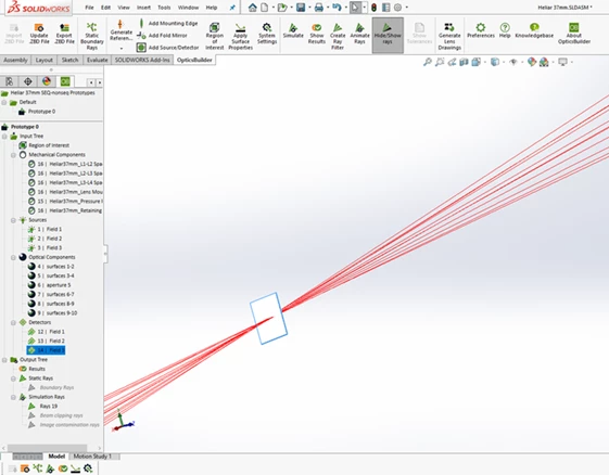
- Revamped 37mm Heliar (Solidworks and Creo)
2 Tools, Features, and Capabilities
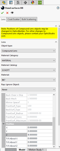
2.1 Positional Changes for Compound and Boolean Objects
Change the positioning of imported Compound and Boolean Objects within your CAD platform
OpticsBuilder 21.3 now offers users the ability to change the X, Y, Z positioning and angles of any optical object with the classification type of Compound or Boolean. For objects in OpticStudio that do not have a non-sequential counterpart, they will be converted to Compound and/or Boolean lenses. While these object types currently have limited ability to be edited within OpticsBuilder because changes to the optical information may break the link between the parent and child portions of the object, in OpticsBuilder 21.3 we provide the ability to move these objects within the CAD space in an X, Y, Z position or to tilt the objects in their X, Y, Z position. This can be especially useful for systems containing mirror objects with asymmetric or off-axis apertures which often convert to Compound and/or Boolean lenses. Such objects are commonly used in systems with tight space constraints in which the mirror needs to fit inside of tight mechanical enclosure; the mechanical engineer can now independently move the mirror and ensure that optical system performance remains intact. These improvements are available in both Solidworks and Creo versions of OpticsBuilder.
2.2 User Experience Improvements - Optics Manager
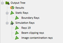
Better descriptions of rays in the Optics Manager
The Optics Manager, on the left-hand side of your CAD platform, is akin to your feature tree. It holds all the sources, detectors, optical, and mechanical components. It also displays the rays available in the OpticsBuilder session. Some rays are static like the Boundary Rays, others are dynamic and update when a Simulation is run. We wanted to provide some clarity around which rays are static and which are dynamic and so we have displayed these in separate categories: Static Rays and Simulation Rays. We also provided clarity around which rays were created based on a filter you created, so we changed the way these are displayed to have a name: “Filtered Rays.” These improvements are available on both Solidworks and Creo versions of OpticsBuilder.
2.3 User Experience Improvements - Boundary Rays
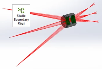
Clearer names and better functionality for Boundary Rays
These Boundary Rays load with a .ZBD file that was generated from Sequential Mode in OpticStudio. These are a static ray set and allow the user to start designing and placing mechanical components immediately around the optical design. Once mechanical components have been designed or placed within the assembly, OpticsBuilder allows users to run dynamic raytracing through the Simulation tool. To minimize confusion about the purpose and function of these different ray set options, we have renamed the “Boundary Rays” button to “Static Boundary Rays.” These also used to hide/show when clicking the “Hide/Show Rays” tool for the static ray set, so we wanted to separate out that functionality. Users may now hide/show their boundary rays by clicking on the “Static Boundary Rays” button only. Additional bugs were fixed for the boundary rays where editing the size or color of the rays caused them to disappear from the graphics area. These improvements are available on both Solidworks and Creo versions of OpticsBuilder.
2.4 User Experience Improvements - Mechanical Edge Tool
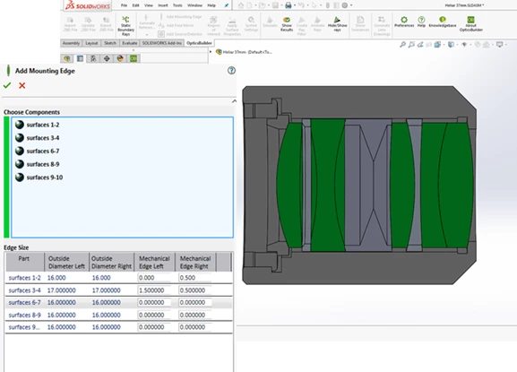
Improved experience when using the Mechanical Edge tool
The Mechanical Edge tool allows users to add a flat mechanical edge to their optical components for the purposes of assembly. The Mechanical Edge tool used to allow users to make changes to the edges by adjusting either the outer diameter value or by adding material beyond the clear aperture of the optical components, called the Mechanical Edge. To make this more user friendly, we now allow users to add material only to the clear aperture and we then display the outer diameter value. The outer diameter values dynamically update as changes are made to the mechanical edge values. OpticsBuilder also used to list the surfaces numerically; this has been updated to call these surfaces “left” and “right.” These improvements are available on both Solidworks and Creo versions of OpticsBuilder.
2.5 Better Source and Detector Visualization
Added quick source and detector visualization aide
If you need to make changes to a source or detector within OpticsBuilder, you can now select the source or detector from the Optics Manager and see it highlighted in the graphics area. This allows you to move through your workflow faster, by quickly identifying the correct source or detector in the system and then editing the properties of this object through the Optics Manager (for systems imported as non-read only). This is available on the Solidworks version of OpticsBuilder. Creo already natively allows users to select sources and detectors and see them highlighted in the graphics area.
3 Bug Fixes
OpticsBuilder for SOLIDWORKS 21.3 includes the following bug fixes:
- Mechanical Components – Our new Ultra Short Throw Projector sample file was having issues saving the mechanical components to the .ZBD file during export. This issue is now resolved.
- Edit/View Optical Components PMP – The PMP for edit/view optical components was slow to open. Improvements have been made to the speed in which this PMP can be opened. For lenses that had active flags for “Rays Ignore Object” and “Do Not Draw Object”, the edit optical components PMP was not available and is now fixed.
- Solidworks Crash – If a user ran a simulation, then modified a ray filter and saved the .ZBD file, upon reimport of this file, Solidworks would crash.
- Edit position of Boolean object preview – When editing the position of a Boolean object, the preview of the change was not showing correctly in the graphics area.
- Ray Filtering – The PMP available when you were setting up your ray filter was slightly different than the PMP shown when you edit a ray filter. We have synchronized these to offer the same tools.
- Scatter Profiles – If a user loaded a .ZBD file that contained mechanical components which already had scatter profiles defined and then modified the scatter profiles, the modifications were not applying to the mechanical parts during the Simulation.
- Zemax Server – If a user opened/closed the view/edit optical properties PMP several times, it would create an error message “Zemax server ID down.” This has been resolved.
OpticsBuilder for Creo 21.3 includes the following bug fixes.
- Multiple pop-up messages – For some customized environments, multiple pop-up messages would show during all user interactions with OpticsBuilder due to a Creo configuration setting. This has now been resolved and multiple pop-up messages will no longer show.
- Export .ZBD File tool – A Source Diffractive that was customized within OpticsBuilder was exporting into the .ZBD file in a size smaller than the created output. Additionally, when exporting a .ZBD file, we have set the tool to turn on a flag that ignores errors on the OpticStudio side. This allows users to import the .ZBD file into OpticStudio and not receive unnecessary error messages.
- Update .ZBD File tool – If a user had constrained mechanical parts to their optical components and then ran Update .ZBD File with a new file that had removed the optical or mechanical component, the constraint between them was not removed and would cause error messages from Creo. We have implemented a fix that will remove a constraint if the updated .ZBD file removes a component so that users will not get error messages and have to manually remove the obsolete constraints.
- Creo Crash – If a user imported a .ZBD file into Creo and then tried to add a large mechanical assembly to it, it would cause Creo to crash. If a user chose to Update .ZBD File and then cancelled the update during the “Updating Part” stage, Creo would crash. If a user imported a .ZBD file into OpticsBuilder and then ran the Update .ZBD file tool twice in the same session, it would cause Creo to crash. These have all been resolved
- Optomechanical components – Users were unable to apply scatter data onto optomechanical surfaces with indexes greater than the number of surfaces in the original optical part. We have also updated the view/edit optical properties window for optomechanical components to improve the user experience. In addition, we have improved the tooltip given while hovering on optomechanical components in the Optics Manager to give users more information and directions to act.
- Source Object Creation – The Source Object component type was not importing correctly into OpticsBuilder and would fail during the geometry creation process. This has now been resolved.
- Sub-assembly mode – The view/edit optical properties window was not opening if the user was in the sub-assembly level of the design.