
Released: May 19th, 2020
1 CAD Expansion
1.1 OpticsBuilder for Creo
Users may now use OpticsBuilder on PTC Creo Parametric
OpticsBuilder 20.2 expands to PTC Creo Parametric versions 4, 5, and 6. Feature parity between SOLIDWORKS and Creo is complete with this launch. For more detailed information on OpticsBuilder for Creo, please visit the MyZemax Learning Path Getting started with OpticsBuilder.
2 Tools, Features, and Capabilities
2.1 Drawing Generation in CAD: Part Mode
Create automatic drawings in both assembly and part mode in CAD
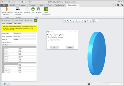
OpticsBuilder 20.2 now offers the ability to use the automatic push button creation of optical drawings feature while in part mode. This allows the user to open up a single optical element from their assembly and create a drawing that automatically adds optical manufacturing data brought in from OpticStudio via the .ZBD file. Users may use the automatic drawing feature in part mode to create automatic drawings using the OpticsBuilder templates, the CAD templates in SOLIDWORKS, or their own custom templates. The Generate Lens Drawings button can be found in the Creo Ribbon or the SOLIDWORKS Command Manager. The new part mode drawing functionality is shown in Figure 2.1.a.
2.2 Generate Reference Geometry in CAD: Part Mode
Create reference geometry in both assembly and part mode in CAD
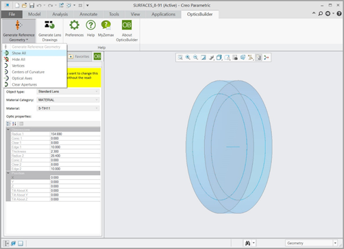
OpticsBuilder 20.2 now offers the ability to generate reference geometry while in part mode. This allows the user to open up a single optical element from their assembly and use optical reference geometry for mechanical component design by measuring and mating mechanical components to the optical assembly within CAD. Users may generate reference geometry such as optical vertices, centers of curvature, optical axis, and clear apertures. The Generate Reference Geometry button can be found in the Creo Ribbon or the SOLIDWORKS Command Manager. The new part mode Generate Reference Geometry function is shown in Figure 2.2.a.
2.3 Comments Pop-Up
Improve communication between OpticStudio users and CAD users by sending a comment with the .ZBD file
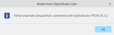
OpticStudio users are able to add comments into the .ZBD file during Prepare for OpticsBuilder. In the OpticsBuilder 20.1 release, this comment is available to view by navigating to System Settings > Design Settings. With the 20.2 we have added in a pop-up window that displays the comments attached to the file after converting and building the file in CAD. This ensures that the communication is seen if available. If there aren’t any comments attached to the file, the user will not see a pop-up comments window. The comments pop-up window is shown in Figure 2.3.a.
3 Usability
3.1 Region of Interest: Multiple Selection
Improved user interface and experience when selecting components to include during simulation
OpticsBuilder previously used a boundary box with draggable edges in the graphics area that allowed users to include components during the simulation function. This boundary box was difficult to use and had low accuracy, so we have removed it. In its place we have implemented the ability to click and drag your mouse to multi-select components to include in the Region of Interest. The new click-and-drag multiple selection function is shown in Figure 3.1.a.
3.2 Hide/Show Button for Simulated Rays
Hide or show simulated rays with the push of a button
Similar to the Boundary Rays button, in 20.2 we introduce the Hide/Show Rays button which allows users to hide or show rays that were generated during the Simulation function with the push of a button. This functionality allows users to more easily analyze in the graphics area how their mechanical components affect the optical performance by viewing or hiding simulated rays created within OpticsBuilder. The Hide/Show Rays button can be found in the Creo Ribbon or the SOLIDWORKS Command Manager. The new Hide/Show Rays button is shown in Figure 3.2.a.
4 Performance and Stability Improvements
OpticsBuilder 20.2 includes the following improvements:
Components supported in both OpticsBuilder for SOLIDWORKS and OpticsBuilder for Creo:
- Grid Sag Lens
- Grid Sag Lens 2
5 Bug Fixes
OpticsBuilder for SOLIDWORKS 20.2 includes the following bug fixes:
- Modified scatter profile causing crash – SOLIDWORKS would crash while opening, converting, and building a .ZBD file if it contained a mechanical component with a scatter profile that had been modified since the last time it was opened. This issue is now fixed.
- Region of Interest: Crash when boundary box is moved– By removing the original boundary box and implementing the functionality to click-and-drag for multiple selection in Region of Interest, the crash issue was resolved.
- Simulations sometimes fail and close – When running a simulation, it would sometimes fail and then close the feature window.
- An updated system was considered modified after simulation – When updating a .ZBD file, OpticsBuilder would consider the updated file as a modified after running a simulation. OpticsBuilder now considers updated .ZBD files as new files after running a simulation.
- Crash after generating second drawing – If a user generated a drawing, closed the drawing window and then regenerated a drawing on the same component, SOLIDWORKS would crash. OpticsBuilder no longer causes SOLIDWORKS to crash if a secondary drawing is generated.