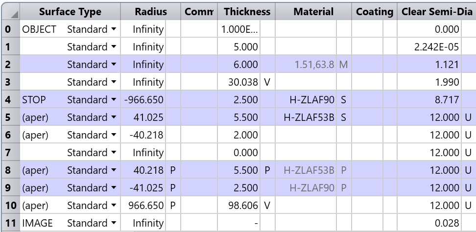
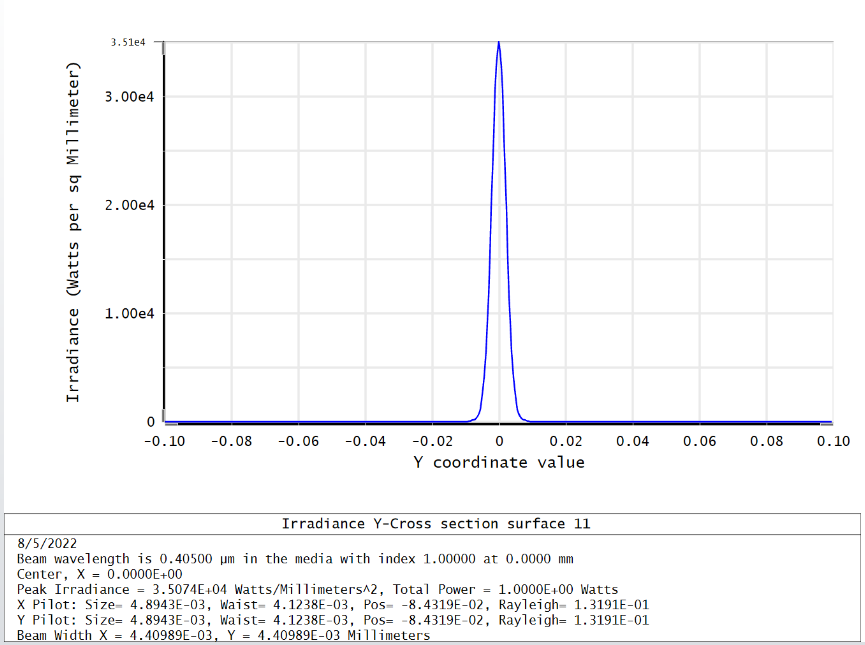
I use double glued lens pairs to focus the laser. The initial settings are shown in Figure 1, and the pop results are shown in Figure 2
Figure 1
Figure 2
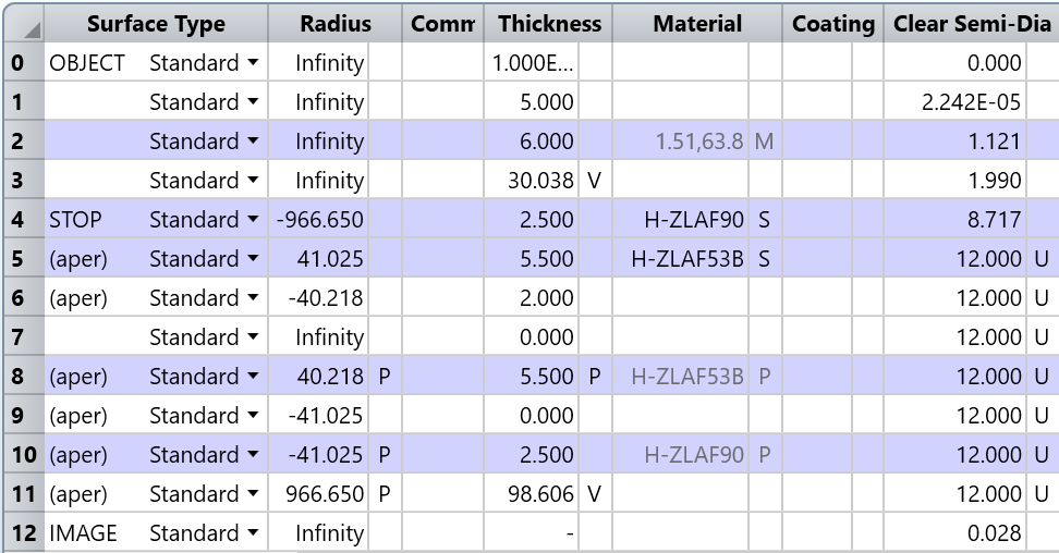
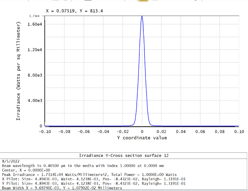
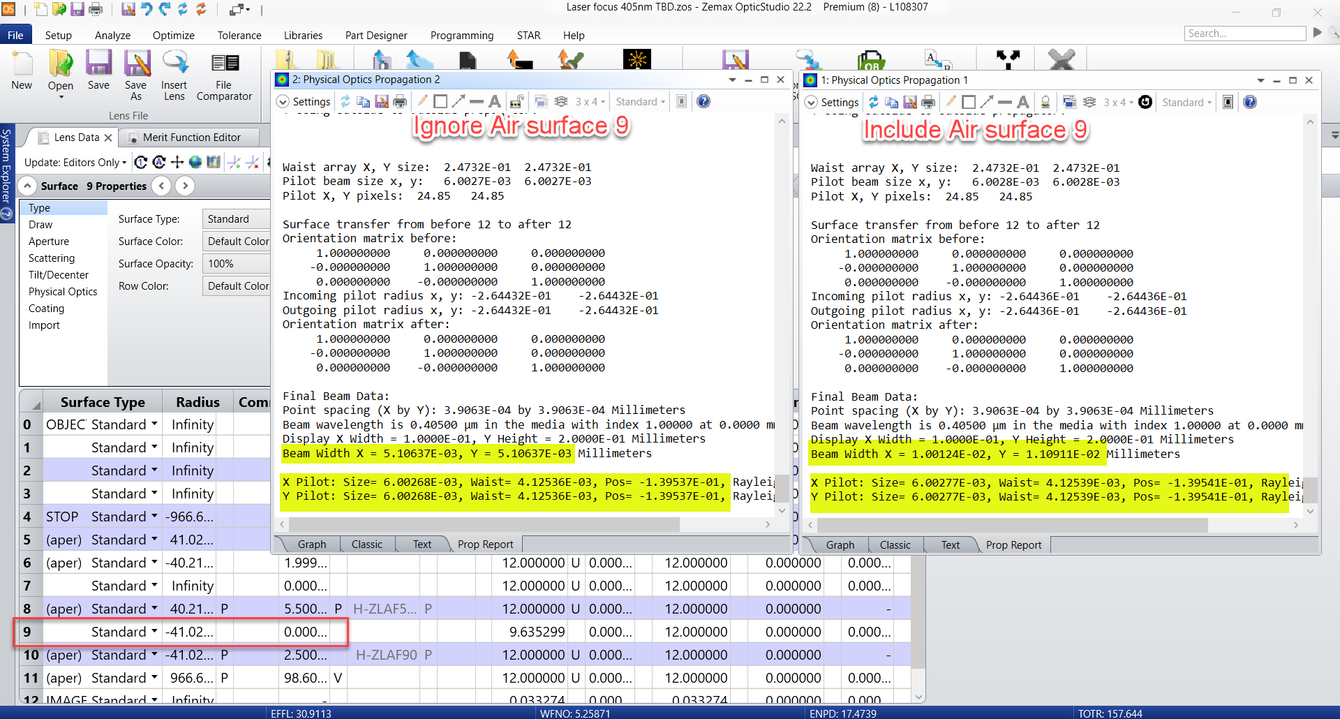
Next, we plan to separate the latter pair of doublets to improve the focusing quality. As a result, when a new air surface is inserted, we find that the pop beam becomes worse. As shown in Figure 3 and Figure 4
Figure 3
Figure 4
I am confused. Why POP simulation results of laser focusing system different?
Best answer by Hui Chen
Hi @luming.ma
Thank you for your post!
I looked at the file you attached. This is an interesting question. I played with the file and can see the same behavior you described. By adding an Air surface of 0 thickness in the last doublet between the original surf 8 and 9, the POP reported Beam Width changed quite a bit at the image plane, from ~5um (without the air gap in the last doublet) to 10 um when including the air gap of 0 mm. If you look at the Propagation Report, you can see the Pilot beam info also changed slightly between the two cases.
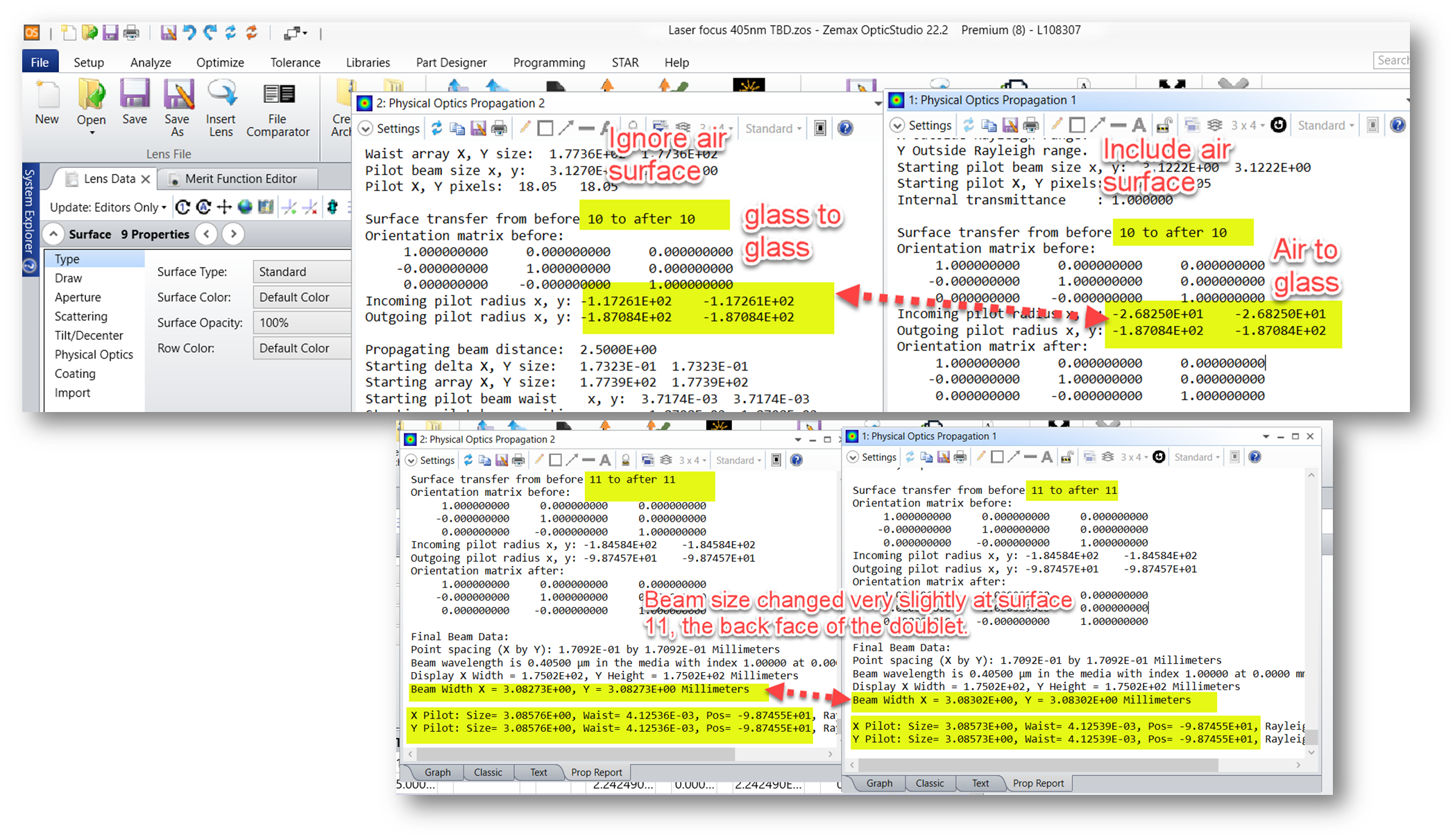
If I look at any other ray based analyses, like Spot Diagram, Wavefront map, they are identical with or without the dummy 0mm air surface which is expected. So this seems to indicate that POP algorithm has challenge constructing probing ray sets to cross over from front glass to dummy air and then from dummy air back to glass. If we compare the Propagation report side by side, if we set the End Surface to surface 11, which is the back face of the doublet, you can see the reported Beam Width on surface 11 starts to vary very slightly between the two cases. This seems confirming the change of the final beam width on surface 12 is caused by POP algorithm crossing from glass to dummy air then back to glass. Though the beam width only shows very slight change on surface 11, 0.3um variation out of 3mm beam, the last propagation of 98 mm from surf 11 to surf 12 is quite long, considering the ending beam Rayleigh range is relatively short, ~ 0.132mm, so it’s possible a 0.3um starting beam size variation on surf 11 might cause a large beam size change at surface 12.
That said this behavior is curious so I would like to investigate a bit more. It’s difficult for me to be certain but my bet is on the slight variation in POP probing ray set construction when inserting a dummy air surface of 0 thickness. You can find some brief discussion on how POP uses Probing rays in the help file at The Analyze Tab (sequential ui mode) > Laser and Fibers Group > About Physical Optics Propagation > Propagation Through Arbitrary Optical Surfaces.
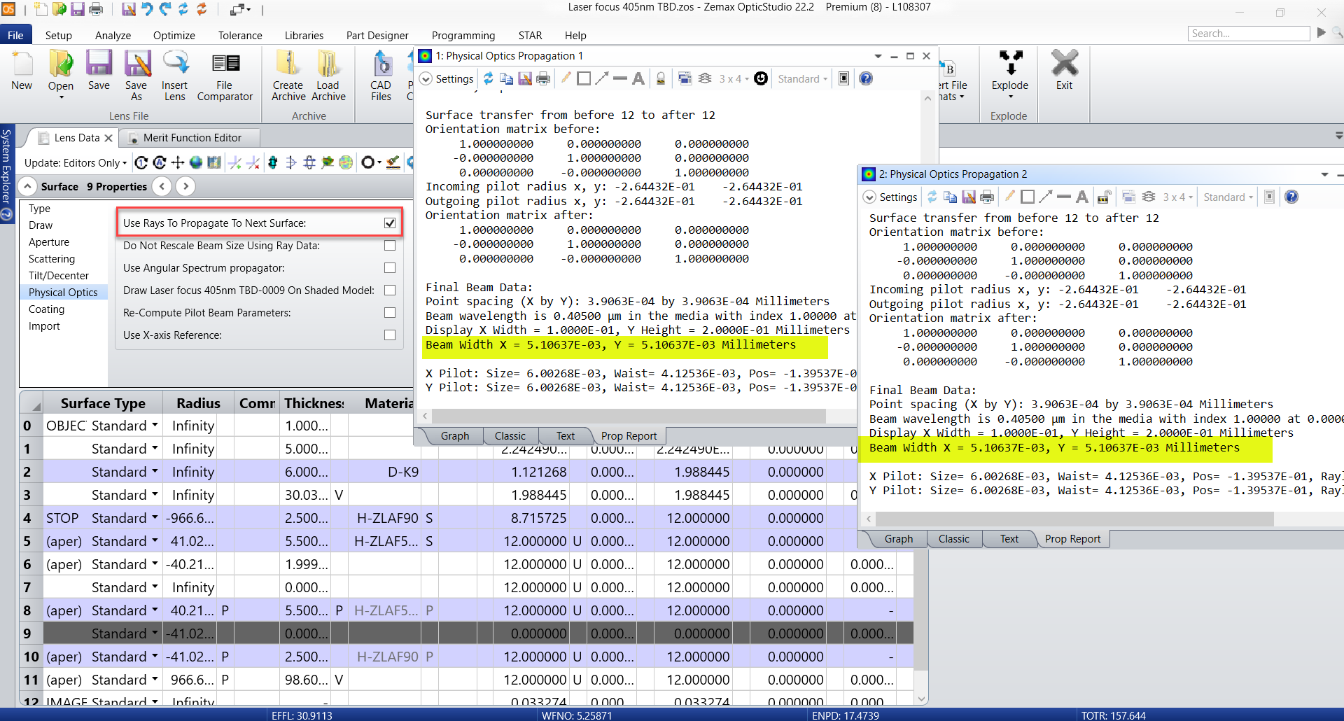
For now, I was thinking if you could try checking this Use Rays To Propagate to next surface option on the dummy air surface 9. When this option is enabled, with or without this air surface 9 will lead to the same Beam Width reported on Image surface 12 as shown below.
I looked at the file you attached. This is an interesting question. I played with the file and can see the same behavior you described. By adding an Air surface of 0 thickness in the last doublet between the original surf 8 and 9, the POP reported Beam Width changed quite a bit at the image plane, from ~5um (without the air gap in the last doublet) to 10 um when including the air gap of 0 mm. If you look at the Propagation Report, you can see the Pilot beam info also changed slightly between the two cases.
If I look at any other ray based analyses, like Spot Diagram, Wavefront map, they are identical with or without the dummy 0mm air surface which is expected. So this seems to indicate that POP algorithm has challenge constructing probing ray sets to cross over from front glass to dummy air and then from dummy air back to glass. If we compare the Propagation report side by side, if we set the End Surface to surface 11, which is the back face of the doublet, you can see the reported Beam Width on surface 11 starts to vary very slightly between the two cases. This seems confirming the change of the final beam width on surface 12 is caused by POP algorithm crossing from glass to dummy air then back to glass. Though the beam width only shows very slight change on surface 11, 0.3um variation out of 3mm beam, the last propagation of 98 mm from surf 11 to surf 12 is quite long, considering the ending beam Rayleigh range is relatively short, ~ 0.132mm, so it’s possible a 0.3um starting beam size variation on surf 11 might cause a large beam size change at surface 12.
That said this behavior is curious so I would like to investigate a bit more. It’s difficult for me to be certain but my bet is on the slight variation in POP probing ray set construction when inserting a dummy air surface of 0 thickness. You can find some brief discussion on how POP uses Probing rays in the help file at The Analyze Tab (sequential ui mode) > Laser and Fibers Group > About Physical Optics Propagation > Propagation Through Arbitrary Optical Surfaces.
For now, I was thinking if you could try checking this Use Rays To Propagate to next surface option on the dummy air surface 9. When this option is enabled, with or without this air surface 9 will lead to the same Beam Width reported on Image surface 12 as shown below.
I try to check “Use Rays To Propagate To Next Surface” , the result is better. As you bet, the slight variation in POP probing ray set construction when inserting a dummy air surface of 0 thickness.
Actually, I want to improve the laser quality by inserting a dummy air and set the thickness as a variable. It seems that I should learn more about the POP mode in ZEMAX.
Anyway, Thank you for your help! And have a good day!