why these configuration showing image upside down. while I am using two mirror in both .

why these configuration showing image upside down. while I am using two mirror in both .
Best answer by David.Nguyen
Hi Tariq,
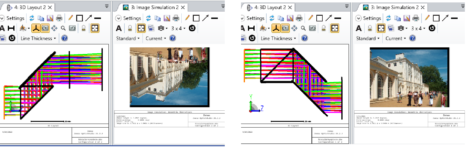
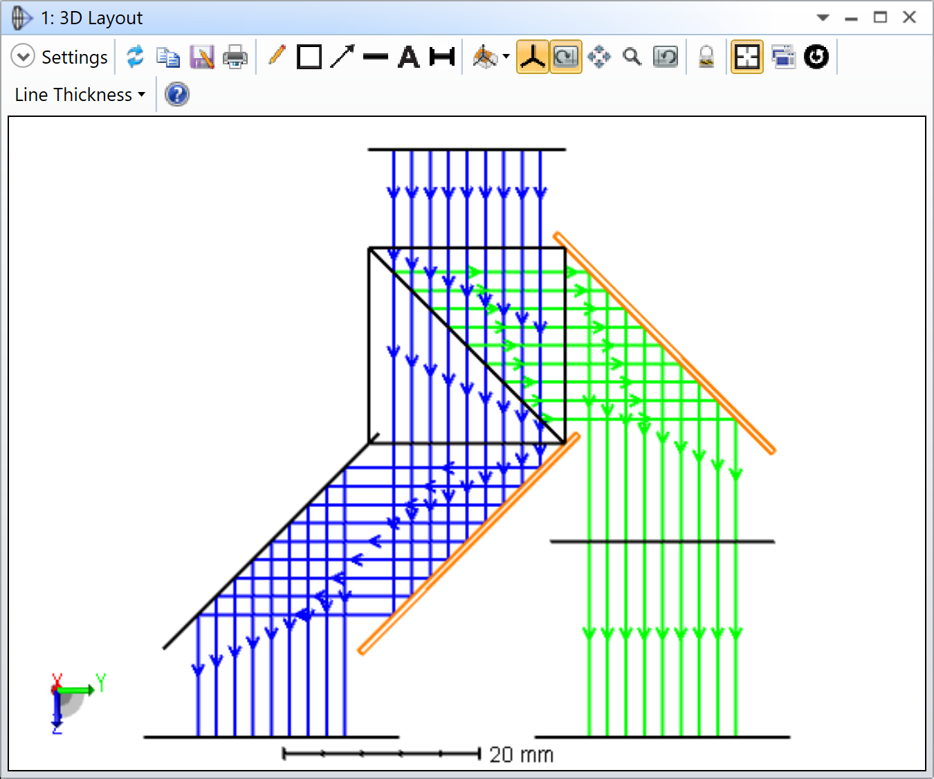
Thank you for sharing your file. When looking at your design, one thing that struck me is your Configuration 2. Here is a 3D Layout of Configuration 2 with Fletched rays and Field 1 only (for clarity):
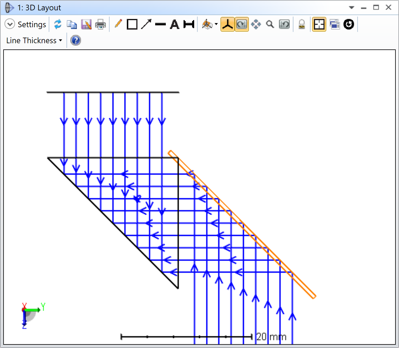
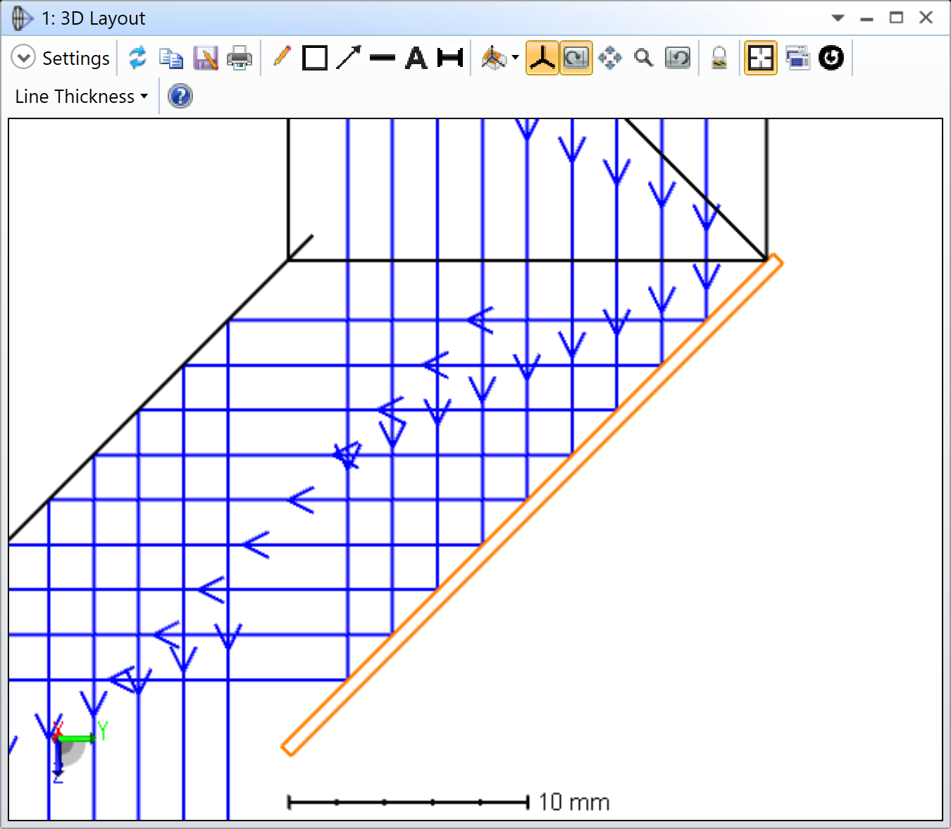
Can you see what is happening? After the beam-splitting cube, the rays propagate backward. Another red flag is the mirror surface, highlighted in orange. With a regular mirror surface, the rays are supposed to reflect off the first surface of the mirror, and not the back one as in your Configuration 2. By comparison, this is what the mirror surface looks like in your Configuration 1:
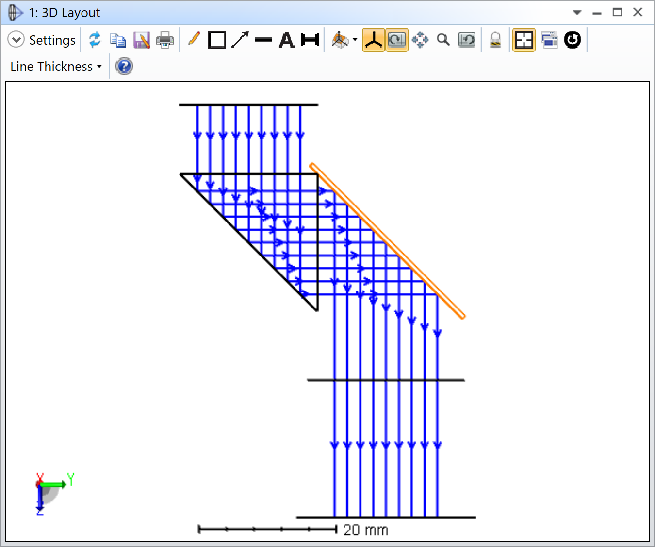
This would be the correct way of defining the mirror surface. It is hard to say why this is happening, but I noticed some strange Multi-Configuration operands, such as your second PRAM operand, which uses a Pick-up solve with a factor of 3. This operand controls the Tilt About X of the Coordinate Break after the splitting surface inside the cube. If we just look at the values, you have a 45 degree Tilt About X before the splitting surface, so it puts the splitting surface at 45 degree, no problem with that. And then, after the splitting surface you have a Tilt About X of -135 degree, which sort of turn the optical axis 180 degree and causes the backward propagation. In OpticStudio, whenever there is a MIRROR surface, you should change the sign of the thicknesses of the subsequent surfaes. In this particular case (Configuration 2), Thickness 4 is +10, and Thickness 7 is still +10 despite the MIRROR surface in between. The 3D Layout sort of make sense, but only because you are propagating backward. What you should do instead, is tilt by another +45 degree in Coordinate Break 7 instead of -135 degree (similar to what OpticStudio does when you add a Fold Mirror), and change the sign of the subsequent thicknesses accordingly (Thickness 7 = -10, Thickness 9 = -10, Thickness 12 = +20, Thickness 17 = +20). This is the result (Configuration 2 only):
Now, the problem is that by changing those Thicknesses, we break Configuration 1, so we need to put those in the Multi-Configuration Editor:
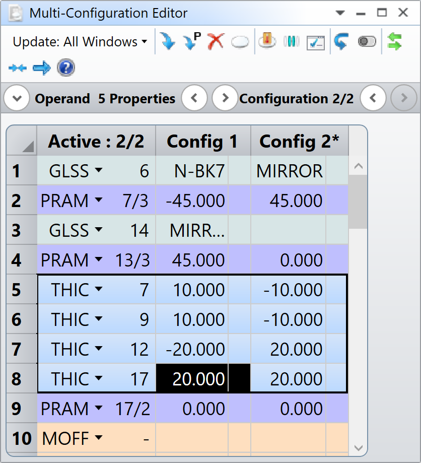
It is interesting to notice where the change in sign happens. In Configuration 1, the MIRROR surfaces are at 11 and 14. Therefore, Thicknesses 12 is negative and 17 is positive again. In Configuration 2, the MIRROR surface are at 6 and 11. Therefore Thicknesses 7, and 9 are negative, and 12, and 17 are positive. This is the result colored by configurations:
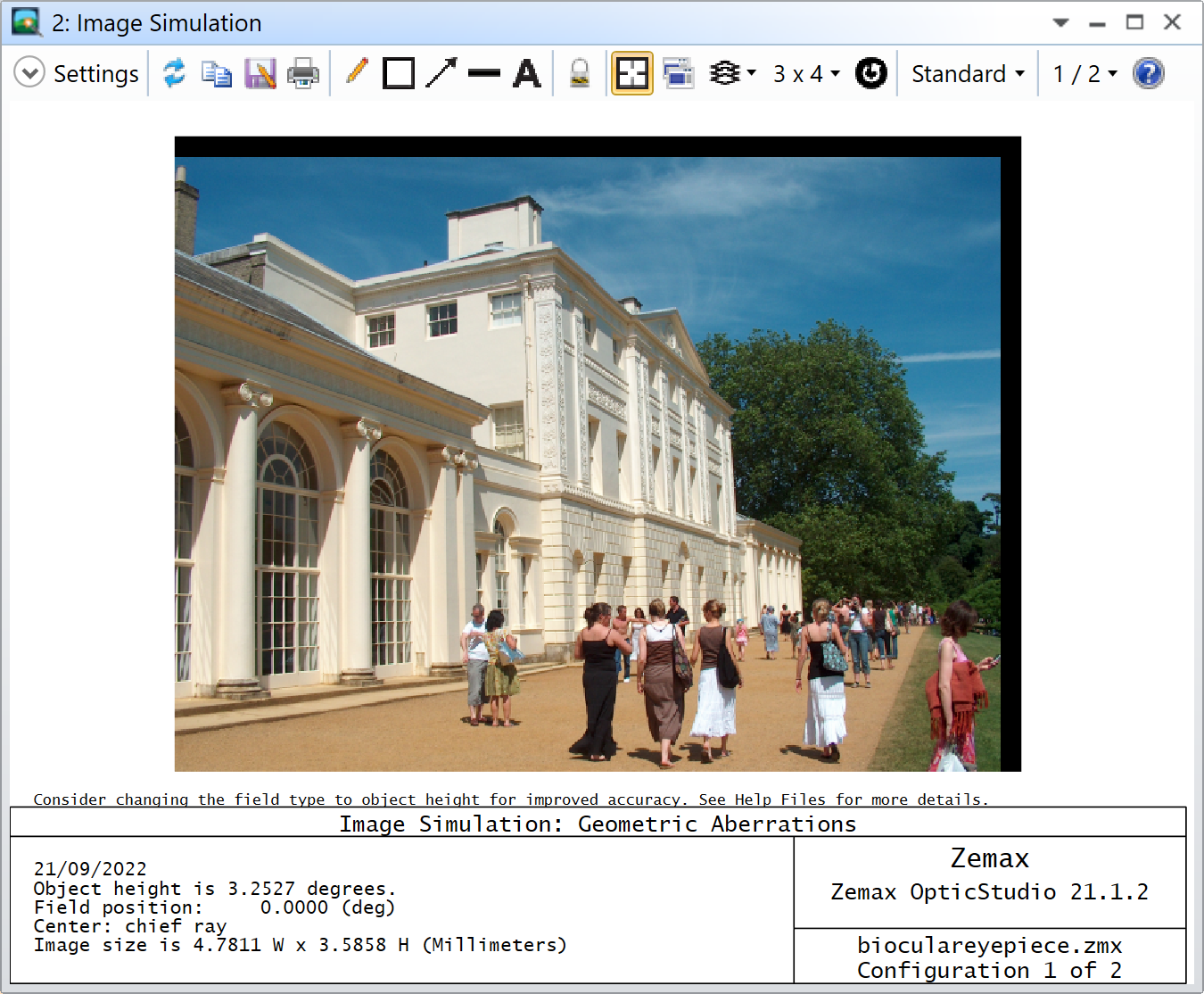
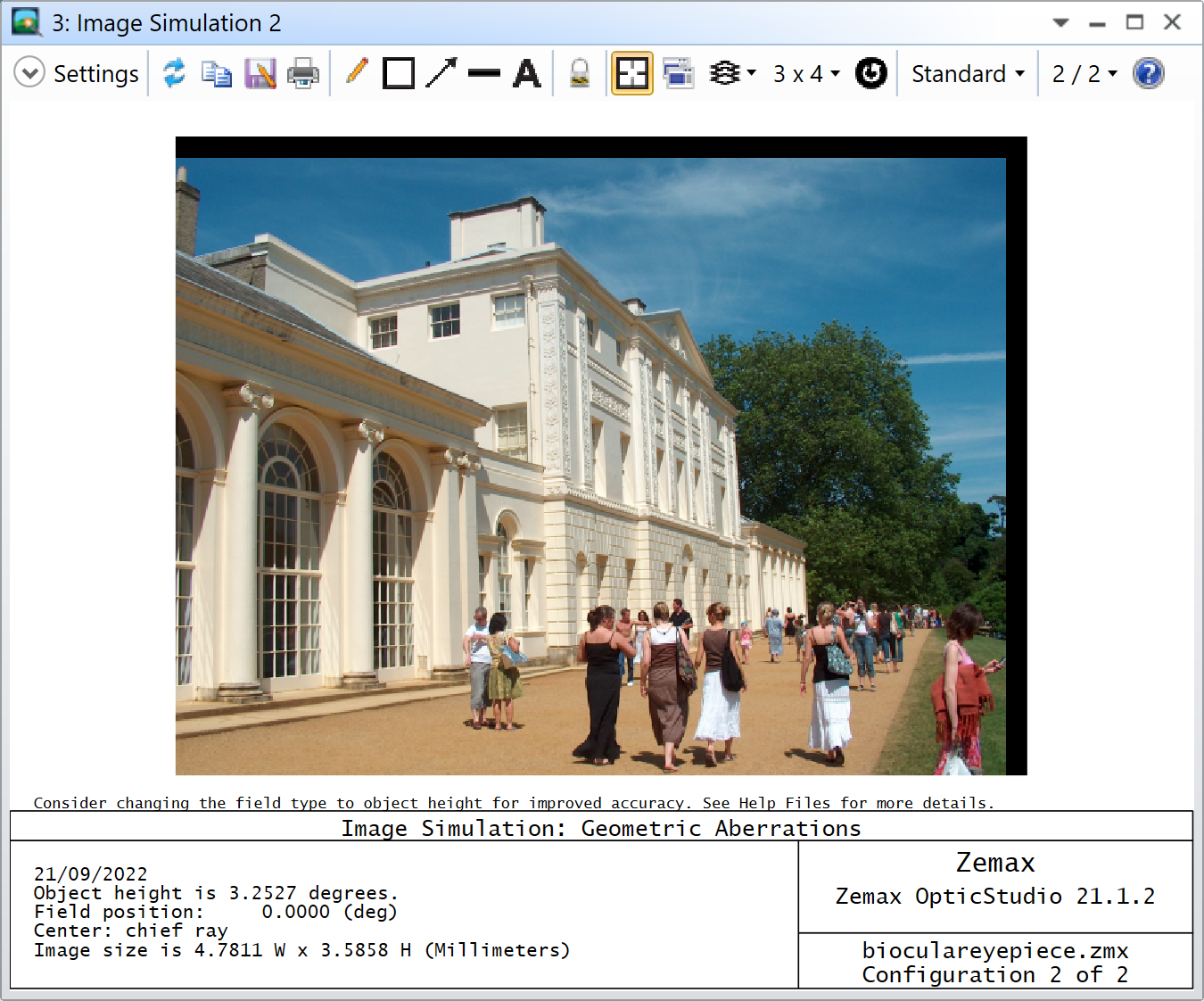
As you can see, the Image Simulation is now correct:
I’m attaching the modified file to my reply. I hope this makes sense.
Take care,
David
Enter your E-mail address. We'll send you an e-mail with instructions to reset your password.
Do not provide any information or data that is restricted by applicable law, including by the People’s Republic of China’s Cybersecurity and Data Security Laws ( e.g., Important Data, National Core Data, etc.).
不要提供任何受适用法律,包括中华人民共和国的网络安全和数据安全法限制的信息或数据(如重要数据、国家核心数据等)。

