Is there a difference between the reported "ray" and "field" coefficients used in polarization ray-tracing through thin-film coatings?

Solved
What are the "ray" and "field" coefficients in the coatings calculation?
 +2
+2Best answer by Allie
There's often confusion on this issue, because thin-film theory and software codes approach this from a different perspective than a ray-tracing engine does.
- In thin-film optics, we usually deal with fields, most normally as plane waves.
- However rays require a subtly different treatment. Rays are infinitesimally small localized points of energy, with position and direction, etc. They see a different world to the world of thin-films.
Take for example the concept of the "point at which the ray hits the surface". In an uncoated optic, that's easy to define with rays: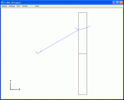
But think now of a simple quarter-wave layer coating (implemented as a separate object 0.25 λ thick) on that surface. If we zoom in on the quarter-wave object we see: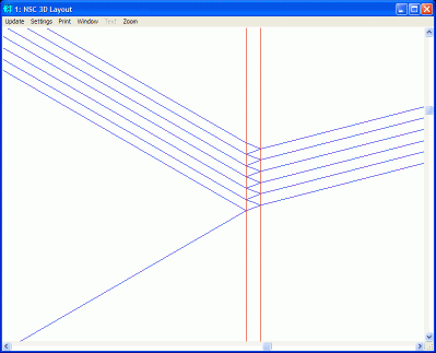
Now in this graphic:
- What is "the" point at which "the" ray hits the surface?
- What is "the" point of splitting?
- Which rays are "the" incident, reflected and transmitted rays?
This graphic illustrates the "field" approach that is used in thin-film optics. An incident plane wave, at some angle, interacts multiple times with the air-coating and coating-substrate interfaces. At each intersection, a transmitted and reflected field is generated, and these are coherently summed. Through the magic of constructive and destructive interference this is resolved into macroscopic reflection and transmission coefficients. The electric field of the incident light is not localized to a single point, but is instead assumed to be large compared to the region of multi-beam interference.
In OpticStudio we refer to these as field coefficients, and they have been checked against thin-film coating codes many times. The thin film convention is to measure the phase shift along the surface normal vector as an imaginary plane wave propagates from the outermost coating layer to the substrate. This convention implies the phase shift is largest at normal incidence, and tapers off to zero by approximately the cosine of the angle of incidence for larger angles of incidence. But ray-tracing requires a somewhat different approach.
The ray-tracing approach is similar to what is shown in the top graphic. Only three rays are involved: the incident, the transmitted and the reflected. You can zoom in as much as you like, that's all you get. The coating itself is not ray-traced, but handled by a separate function.
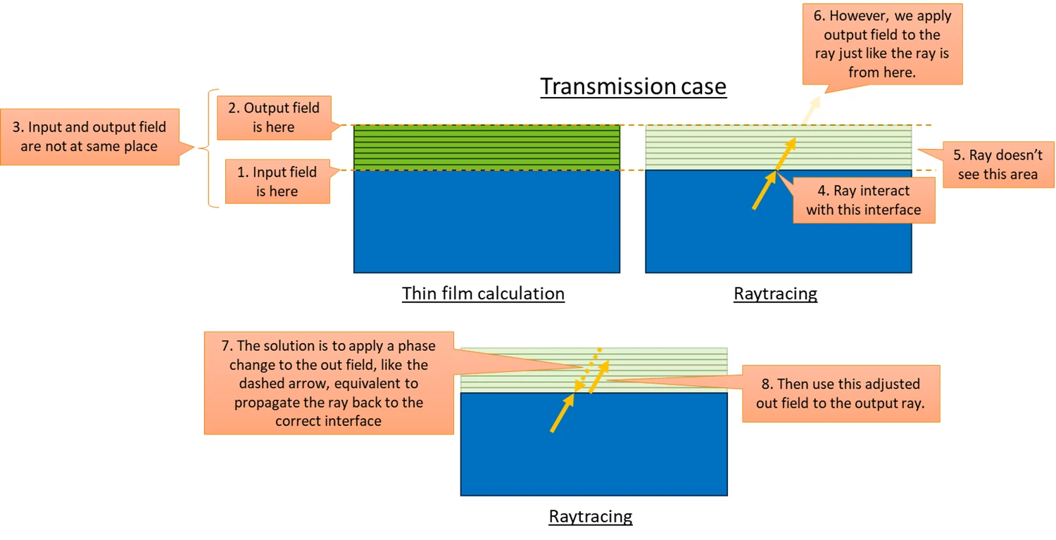
For ray tracing, the optical phase advance or delay is measured along the ray. OpticStudio traces rays directly to the substrate, ignoring the coating and its thickness. The coating is presumed to grow into the space preceding the surfaces. Correctly computing the phase of the ray requires back propagating the electric field to the point the coating begins, and adjusting the coating phase to be measured along the ray vector rather than the normal vector. OpticStudio calls these the ray coefficients. Since optical path length is measured along the ray, and the length of the ray in the coating increases with angle, the ray phase goes as approximately 1/cos(θ). This is the correct convention to use when adding coating phase to optical path length.
Note that OpticStudio reports both the ray and field coefficients in the Polarization Ray-Trace, so you have access to both. The ray coefficients are what you need if you are going to add coating phase to optical path length, and the field coefficients are included for ease of cross-checking with thin-film codes. Note that the retardance S-P is identical whichever calculation you use.
Enter your E-mail address. We'll send you an e-mail with instructions to reset your password.
Need more help?
To Chinese users:
Do not provide any information or data that is restricted by applicable law, including by the People’s Republic of China’s Cybersecurity and Data Security Laws ( e.g., Important Data, National Core Data, etc.).
不要提供任何受适用法律,包括中华人民共和国的网络安全和数据安全法限制的信息或数据(如重要数据、国家核心数据等)。