Solved

Wavefront map for arbitrary surface

  • 29 November 2023
  • 4 replies
  • 141 views

Hello there Zemax community,

I have an understanding question that maybe you can help me get through. 

I know that the wavefront map evaluated at the image plane corresponds to the optical path difference or the difference in wavefront with respect to an ideal spherical wavefront with its origin positioned at the exit pupil. In this way, the wavefront map provides an indication of how does the wavefront deviate from the case of an ideal spherical wave (please let me know if my understanding is not accurate)

How does this work for wavefront maps evaluated at different surfaces from the final image surface? What is the reference position in this case? For surfaces different than the image surface, does the reference spherical wavefront still holds and makes sense? 

Finally, I would like to know if there is any way to obtain the “raw wavefront” of the field. Instead of obtaining the difference with respect to a reference, is it possible to extract the phasefront from the field at any given surface position within an optical system?

Any comment or feedback will be highly appreciated!


icon

Best answer by Mark.Nicholson 29 November 2023, 19:41

View original

4 replies

Userlevel 7
Badge +3

Hi CJ,

Your understanding is basically correct. OpticStudio does a paraxial raytrace of the system to establish all the first order properties such as EFFL, f/# and pupil locations and sizes. They are then used by all field points, which is why you get aberrations such as field curvature and coma. These fields are ‘aberrated’ with respect to the same paraxial reference.

For surfaces other than the image surface, we use a paraxial thickness solve after the surface to come to ‘best focus’ and then do the same paraxial setup with respect to this new image surface.

The difference with respect to the paraxial reference sphere is indistinguishable from the ‘Raw’ data. If the reference sphere radius is 50 mm say, and the opd of a ray is lambda/20, then the raw data is just 50 + lambda/20. Using the reference sphere means we focus on the lambda/20, which is the ‘interesting’ part. It also means the calculations can be performed on 64-bit machines as you don’t need to use up all your precision just on the 50 mm figure.

This is entirely analogous to an interferometer with a reference sphere. Try removing the reference sphere and all you’ll get is the bulk path length of the rays: the beam itself won’t show the tiny phase profile on top of the massive constant path length. You need the reference sphere to subtract out the bulk length and leave you with only the variance.

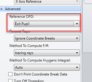
But if you want to do it, look at the System Explorer under Advanced, at the Reference OPD setting:

You may want to experiment with the Absolute and Infinity settings. See the documentation for full details. But the exit pupil refernce is the one to use in all but very odd circumstances :-)

Hope that helps,

  • Mark

Hi Mark, 

Thanks a lot for the nice feedback. Would you mind giving me some additional details about where to look in the documentation? That would be really helpful.

Also, I see that you refer to a paraxial raytrace in order to stablish all of the first order properties of the system. I guess this is always the case irrespectively of whether my system can be considered paraxial or not? 

In my case, I am modeling the scenario of a “Gaussian”-like amplitude point source on axis which has a relatively wide angle of emission, making my problem not paraxial. I guess that for purposes of finding those first order system properties, this does not matter right? 


Userlevel 7
Badge +3

The Knowledge Base is probably the best place to look for deeper understanding. The Help files are descriptive rather then explicative, IMHO.

Gaussian Beams are not raytraced. The equations for GB propagation only involve the GB parameters and the radius of curvature of the surfaces it passes through. You can use Gaussian apodization to make a ray bundle have the intensity profile of a Gaussian beam, but that apodization does not result in a ‘beam waist’.

  • Mark
Userlevel 4
Badge +1

Hi CJ27,

Overall, I’d go with Mark’s suggestion that the Exit Pupil reference is usually the one you want. 

I’d start with this posting: 

I would also suggest these two KBA articles. Only the first one directly addresses your initial question, but you may find the second to be beneficial in your future endeavors.

https://support.zemax.com/hc/en-us/articles/1500005487721-Why-is-the-optical-performance-sometimes-different-at-the-Image-surface-versus-a-co-located-surface-

https://support.zemax.com/hc/en-us/articles/1500005488301-What-does-the-sampling-correspond-to-in-wavefront-based-calculations-

Reply