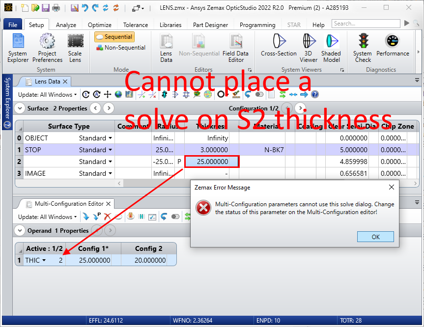
I am simulating a small parabolic mirror design and I am using “Marginal Ray Height” solve type on a surface’s thickness to find the paraxial focal point of my system. I would like to change the thickness of another surface in the system using the multi-configuration tool and see how the focal point location moves by monitoring the changes in my “solve thickness”. However, the multi-config editor doesn’t allow for the “solve thickness” to be set on “solve” mode. Does anyone know a way to work around that? Please, keep in mind that I have an old version of Zemax (2008).
Page 1 / 1
Hi Alexandre,
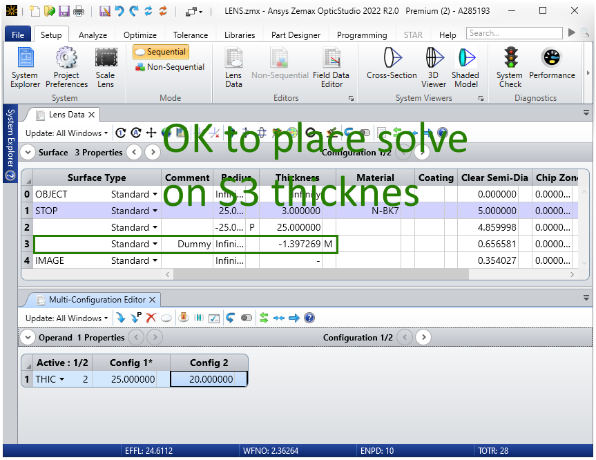
I’m not sure I entirely follow the setup (a picture of the LDE and MCE would help). Since you’re simply trying to use a Marginal Ray Height solve, can you simply add a dummy surface to the LDE which is not controlled by the MCE and then place the solve on the dummy surface?
P.S. I’m also only familiar with OpticStudio and there is not a dedicated “solve” mode in OS so my suggestion might only work for OS.
Michael,
First of all, thank you so much for your feedback. I really appreciate that. I feel that I need to explain better what I am trying to do, so I’ve inserted the following image.
Basically, I am trying to generate a plot (Universal plot for instance) of the variation of a thickness from surface 3 (red square) with respect to the thickness from surface OBJ (blue square) where the OBJ thickness varies according to the MCE’s configs. For each configuration of surface OBJ, the surface 3 thickness should update automatically using the solver “Marginal Ray Height”, but I am not sure that I am constructing this idea correctly using the MCE.
Any thought on that would be greatly appreciated.
v/r,
-Alex
@apbraga:
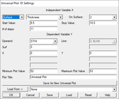
Maybe I don’t understand your question, but if all you want to do is vary the thickness of a surface (prior to the marginal ray solve surface), and see how the marginal ray solve changes the distance to the paraxial focal plane, then you can simply use the Universal Plot feature (which exists in classic Zemax 13, circa 2015) or do something similar with a ZPL script if the Universal Plot is not available. Not sure why you need the Multiconfig tool? (By the way, I don’t see any difference between the MCE solve options with Z13 compared to the latest version of OpticStudio.)
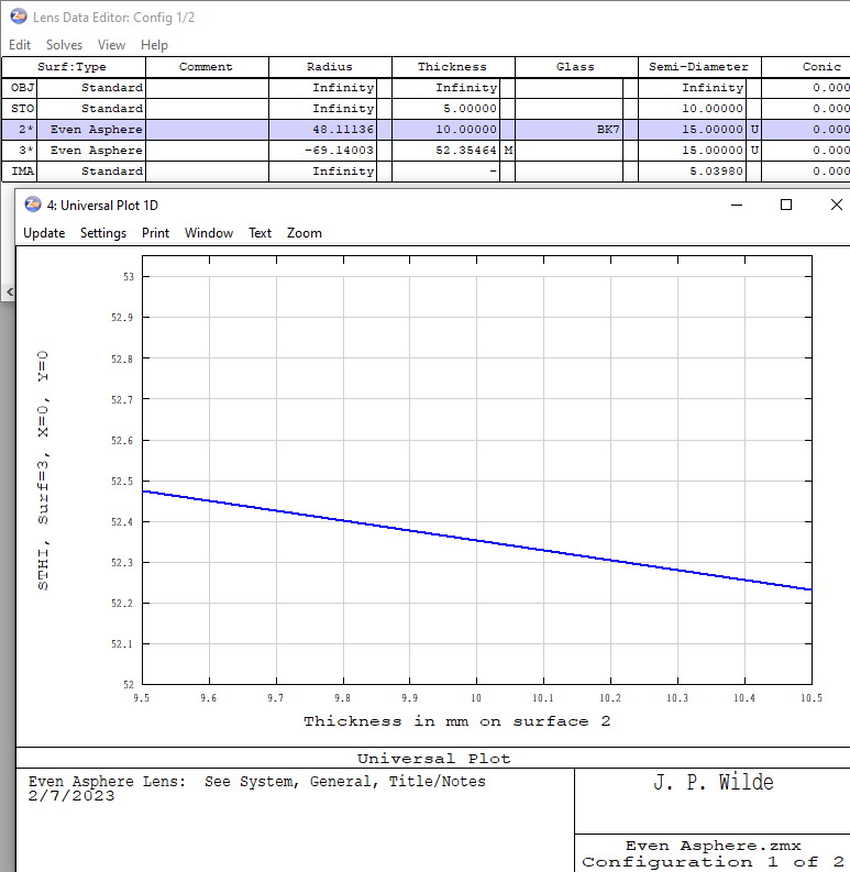
I still happen to have Z13, so here’s an example using this version. In this case I’m using the Even Asphere sample file with a Marginal Ray Solve on Surface 3, and varying the thickness of the lens (Surface 2) in the Universal Plot settings to display the resulting change in Surface 3 thickness:
Here are the results:
The raw data are available in the Text window of the Universal Plot.
Regards,
Jeff
@Jeff.Wilde,
Thank you so much for your recommendation. The universal plot worked perfectly.