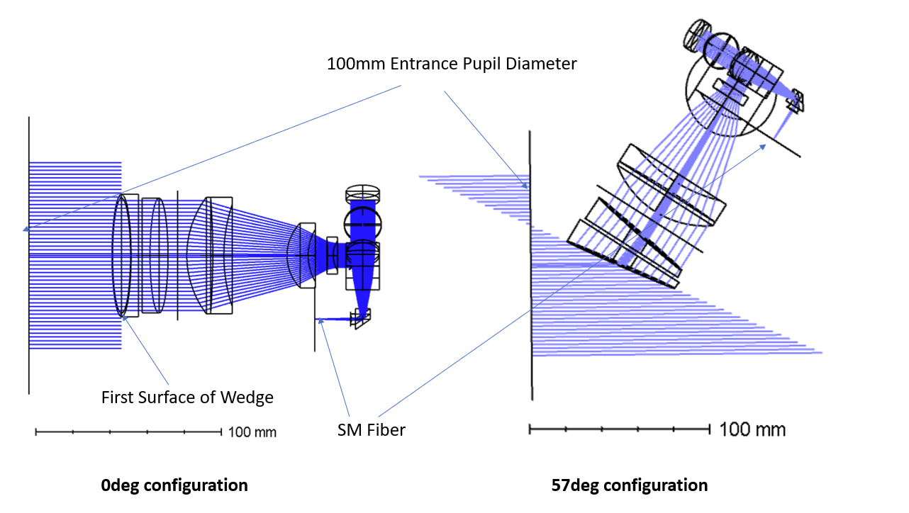
I have an optical system entering through two optical wedges (9deg wedge angle) and going through some focusing optics coupling into a SM fiber. I use the wedges for beam deflection. With a coordinate break I make sure to get the beam to the single mode fiber. I have several configurations to simulate different angle (0deg to 57deg).
With the fiber coupling window I can see the fiber coupling efficiency. From the plots you can see that mainly the first surface of the first wedge causes significant vignetting, which is in addition depending on the angle. At larger angles the aperture of the wedge becomes effectively elliptic, shrinking the short axis with the cosine of the angle. Therefore, also the System Efficiency should drop with the cosine of the angle.
31.5mm the radius of the wedge, 50mm the radius of the aperture. First one at 0deg, second one at 57deg. I added 0.8 to roughly model the Receiver Efficiency:
>> 31.5^2*cos(0/180*pi)/50^2*0.8 ans = 0.31752
>> 31.5^2*cos(57/180*pi)/50^2*0.8 ans = 0.17293
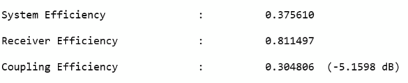
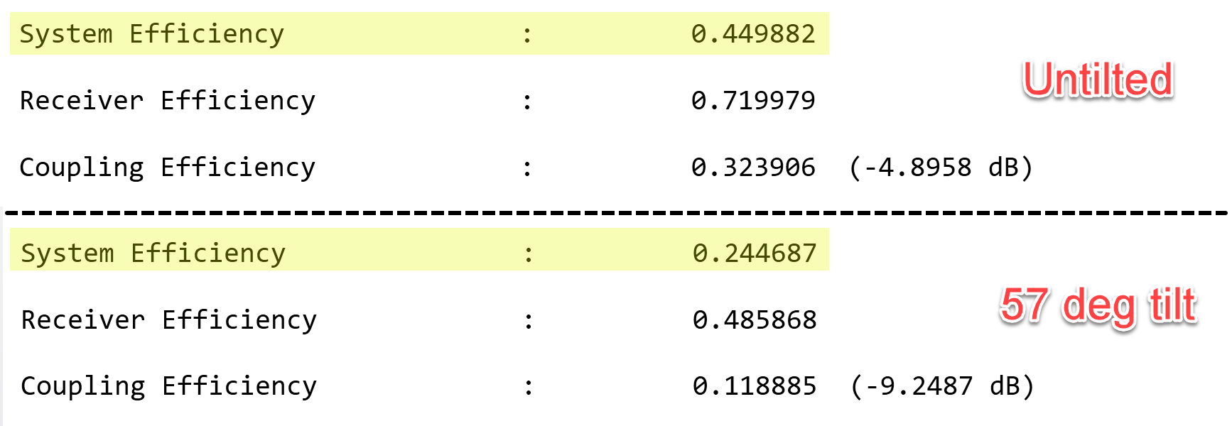
Below the 3D layout I show the two output results of fiber coupling in Zemax.
0 deg angle, with 0.3756 System Efficiency57 deg angle, with 0.3511 System Efficiency
Somehow, these values don’t match with my own octave calculation, which should read 0.31 to 0.17.
Somehow, I don’t get the difference in the calculations. Of course, little difference will be OK, because there will be also some minor other vignetting effects in the system, but my result is 50% loss between 0/57deg, while Zemax shows only ~6% loss between those angle.
Maybe somebody has a hint for me.
Many thanks
Markus
Best answer by Angel Morales
Hi Markus,
Thanks for your post! With respect to your question, it’s a bit hard to diagnose without access to your file. Would that be something you could share either through this post or by opening a ticket by sending an email to support@zemax.com?
If not, no worries. A hint might be the fact that your System Efficiency is relatively equal between your nominal and tilted setups for your file. The System Efficiency is defined by the ratio of energy from the source input (modeled either by a fiber definition in the SMF Coupling tool or as your rays directly from your Object plane) to that which is able to exit through the system. It should be taking into account things like vignetting, your entrance pupil size and position, and more details. So, one thing that could be changing is something like your input ray bundle or entrance pupil size as you’re tilting your lens system.
Just to clarify, what are your settings for the system? Do you have specified an Aperture Type of Entrance Pupil Diameter, or is it set to something like Float By Stop Size? Is your STOP defined somewhere in the middle of the system, and do you have Ray Aiming turned on?
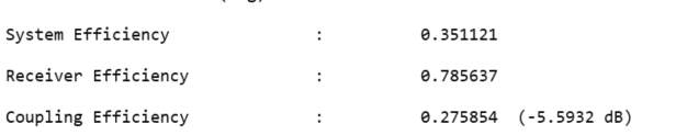
If you want to fix the input aperture of the system to be determined by your input ray bundle, you could consider defining a “dummy STOP” surface in front of the system to act as an Entrance Pupil. You should define this before any Coordinate Break surface. This would set the amount of energy that is coupled into the system entrance as determined by the size of the Entrance Pupil. Any subsequent losses would be from surface apertures vignetting the input beam bundle, reflectance losses if you’re accounting for those, etc. I’ve made a dummy test file below to illustrate this with a Paraxial lens:
The comparison to your file is a bit different since I clearly have different receiver efficiency values between the configurations, but it does demonstrate a difference in system efficiency. Let us know how these thoughts work out or if you have more questions. Thanks!
Thanks for your post! With respect to your question, it’s a bit hard to diagnose without access to your file. Would that be something you could share either through this post or by opening a ticket by sending an email to support@zemax.com?
If not, no worries. A hint might be the fact that your System Efficiency is relatively equal between your nominal and tilted setups for your file. The System Efficiency is defined by the ratio of energy from the source input (modeled either by a fiber definition in the SMF Coupling tool or as your rays directly from your Object plane) to that which is able to exit through the system. It should be taking into account things like vignetting, your entrance pupil size and position, and more details. So, one thing that could be changing is something like your input ray bundle or entrance pupil size as you’re tilting your lens system.
Just to clarify, what are your settings for the system? Do you have specified an Aperture Type of Entrance Pupil Diameter, or is it set to something like Float By Stop Size? Is your STOP defined somewhere in the middle of the system, and do you have Ray Aiming turned on?
If you want to fix the input aperture of the system to be determined by your input ray bundle, you could consider defining a “dummy STOP” surface in front of the system to act as an Entrance Pupil. You should define this before any Coordinate Break surface. This would set the amount of energy that is coupled into the system entrance as determined by the size of the Entrance Pupil. Any subsequent losses would be from surface apertures vignetting the input beam bundle, reflectance losses if you’re accounting for those, etc. I’ve made a dummy test file below to illustrate this with a Paraxial lens:
The comparison to your file is a bit different since I clearly have different receiver efficiency values between the configurations, but it does demonstrate a difference in system efficiency. Let us know how these thoughts work out or if you have more questions. Thanks!