Solved

Understanding Pupil Aberration Fan

  • 5 April 2023
  • 7 replies
  • 461 views

Userlevel 1

Hello,

I have a question regarding Zemax sequential plot “Pupil Aberration Fan”.

a).If I take an on axis field point and a plano-convex lens (plane surface = incident surface = stop) this plot does not show any pupil aberration. 
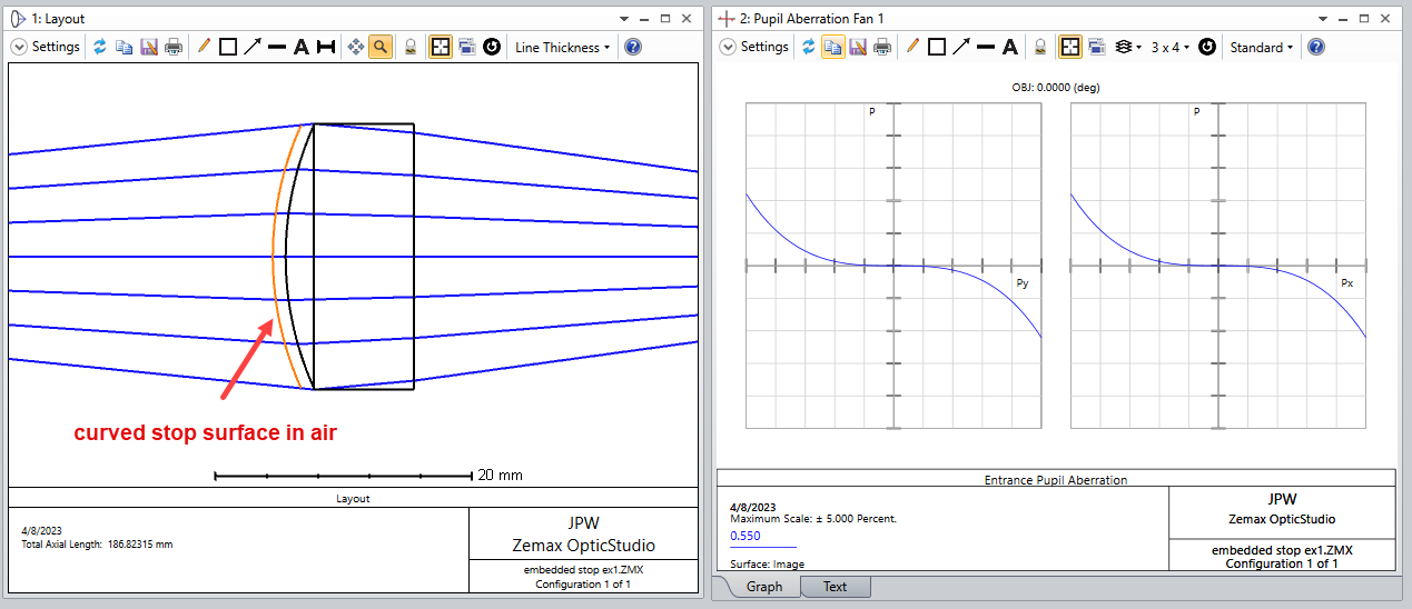
b).If I take the same setup and the same lens, but now with the convex surface as incident surface (=stop), the pupil aberration fan shows pupil aberration.

I do not understand this. From my understanding pupil aberration fan compares the normalized pupil coordinates of a ray passing the physical stop with the normalized coordinates of this ray in the entrance pupil (which is an image of the physical stop).

In both cases a) and b) the stop (=lens diameter) is also the entrance pupil. So there should be no pupil aberration. Can you help me to understand this?

Thanks in advance 
Dirk


icon

Best answer by Mark.Nicholson 5 April 2023, 19:59

View original

7 replies

Userlevel 7
Badge +3

What is your aperture type, and do you have ray-aiming on? If you could share the file it would be a big help

Userlevel 7
Badge +3

@Dirk.Broemme:  Yes, if the stop is a curved lens surface, then pupil aberration can arise:


If you move the stop to a dummy surface with zero thickness, immediately in front of the lens, the pupil aberration vanishes.


However, if we shift this external stop surface a little bit farther to the left, and add curvature (but the stop surface has no optical power since it has air on either side), we see the pupil aberration returns.


This makes sense given how pupil aberration is defined in OpticStudio:

The mapping of a curved stop surface to a flat (paraxial) stop surface has intrinsic distortion, hence pupil aberration.  Here’s the calculation for the example above (2.2% pupil aberration):


In some cases, it is of interest to use a planar stop surface that is embedded inside the lens, which is discussed in this link:  Are you choosing a physical stop?  In this case it is suggested to split the lens into two separate sections that sandwich the planar stop surface.

Regards,

Jeff

Userlevel 7
Badge +3

This is an interesting case. With the stop on its own surface, there is no power between the object and the stop and so no pupil aberrations. With the stop on a surface with power, there is power and hence aberrations.

I would turn on ray-aiming in the example where the stop is the actual lens surface. Remember the object is supposed to radiate into all angles, and so overfill the stop. If you want the limiting ray to be the one that hits the embedded stop, ray-aiming should be on.

Both cases are correct, it just depends on which is the physically correct one for your system.

Mark

Userlevel 7
Badge +3

After giving this problem more thought, I updated my previous response to make some corrections and provide additional detail.

I agree with Mark, any time the stop is chosen in such a way that it produces pupil aberration, then it’s a good idea to turn on ray aiming.

Jeff

Userlevel 6
Badge +2

Hey @Jeff.Wilde & @Mark.Bennahmias 

To continue the conversation a bit, except for “speed” (which isn’t really a modern concern) and Ray Aiming failures (which Zemax is actively addressing):

Is there a time when Ray Aiming shouldn’t used?

Zemax historically has not set Ray Aiming on by default because of speed & failure modes, but if those two considerations are taken off the table, is there a scenario when no Ray Aiming is better than Paraxial Ray Aiming?

Also, what’s a more physically accurate representation of the Exit Pupil...a dummy surface with (virtual) propagation or the actual curved surface itself?  Would Ray Aiming on a curved surface (without a dummy surface) be more physically accurate because you’re mapping the Marginal Ray to the edge of the physical aperture itself and not to a dummy surface?

I’ve seen all combination of files (ray aiming on/off, paraxial vs real RA, dummy surface vs actual surface for the Stop, etc) and it would be nice if the “Zemax Community Brain Trust” could have an agreed upon recommendation for where the Stop should go.  I know there was a discussion about 8 months ago but I think it stopped before a meaningful conclusion:

Are you choosing a physical stop? | Zemax Community

I personally think the only difference between the “virtual propagation” and the “embedded” model is where the Chief Ray is...I also personally think that beyond 3rd order wavefront values which require Chief/Marginal rays, you would be using more robust Centroid-based metrics for your analysis, so the more simple & intuitive virtual propagation is both “good enough” and accurate.  This “virtual propagation” method is more realistic since the Exit Pupil is the image of the Stop from the detector plane and the “image of the Stop” can’t know an “embedded” surface..  I also think you should always use Paraxial Ray Aiming (as long as it doesn’t fail).

Userlevel 1

Hello Marc, hello Jeff and hello MichaelH,

thanks for all of your answers. I forgot to turn on ray aiming!! So I am sorry for my stupid question:-/
I also can recommend this knowledgebase article about ray aiming which I found very helpful:

How to use Ray Aiming – Knowledgebase (zemax.com)

Best regards

Dirk

Userlevel 7
Badge +3

Thanks Dirk! If there’s any power between the stop surface and the object, ray aiming should always be turned on.

Personally I think it should always be on and the user should not be able to turn it off. The case of zero power between the object and stop is so fast that having ray aiming on does not affect things anyway, but could easily be trapped in the code anyway. From the perspective of a 21st century user rather than someone banging away with a 386 or 486 processor and 1 MB of RAM, this switch is otiose now.

But rather than wait for Ansys Zemax to change things, just start OS up, turn ray-aiming on in the file that auto-loads and then just save it as lens.zmx. Never be bothered by 1990-era workarounds again!

Reply