I am a student who is working on an optical design. I have completed the design and wanted to do the ray tracing for it in Zemax. However, when I inserted the surfaces and saw the 3D view, the light rays did not propagate through the imported CAD file and stopped at the beginning of the shape. I realise that the image plane also coincides with the imported body and U am unable to modify the image plane thickness. I am just beginning to learn Zemax and am currently stuck in this situation therefore I ask you to kindly help me out.
SetupThe 3D view
Light stops here
Best answer by David.Nguyen
Hello Hariprasad,
Just one tip if you want to increase your chances of recieving an answer: try to give as much information as possible, and this includes uploading an example file or an *.IGES file that we could try with.
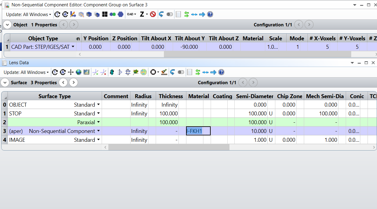
Your lens looks like a TIR lens, I went ahead and downloaded an *.IGES model here, and I set it up in OpticStudio as follows:
The file is also attached to this post for your reference.
The most important thing to adjust is the position of the Exit Port. If the Exit Port isn’t setup correctly, it is most likely the cause of termination for your rays.
This section of the Help File: The Setup Tab > Editors Group (Setup Tab) > Non-sequential Component Editor > Non-sequential Overview > NSC ray tracing in mixed mode (with entry and exit ports) gives a thorough description of the Entrance and Exit ports.
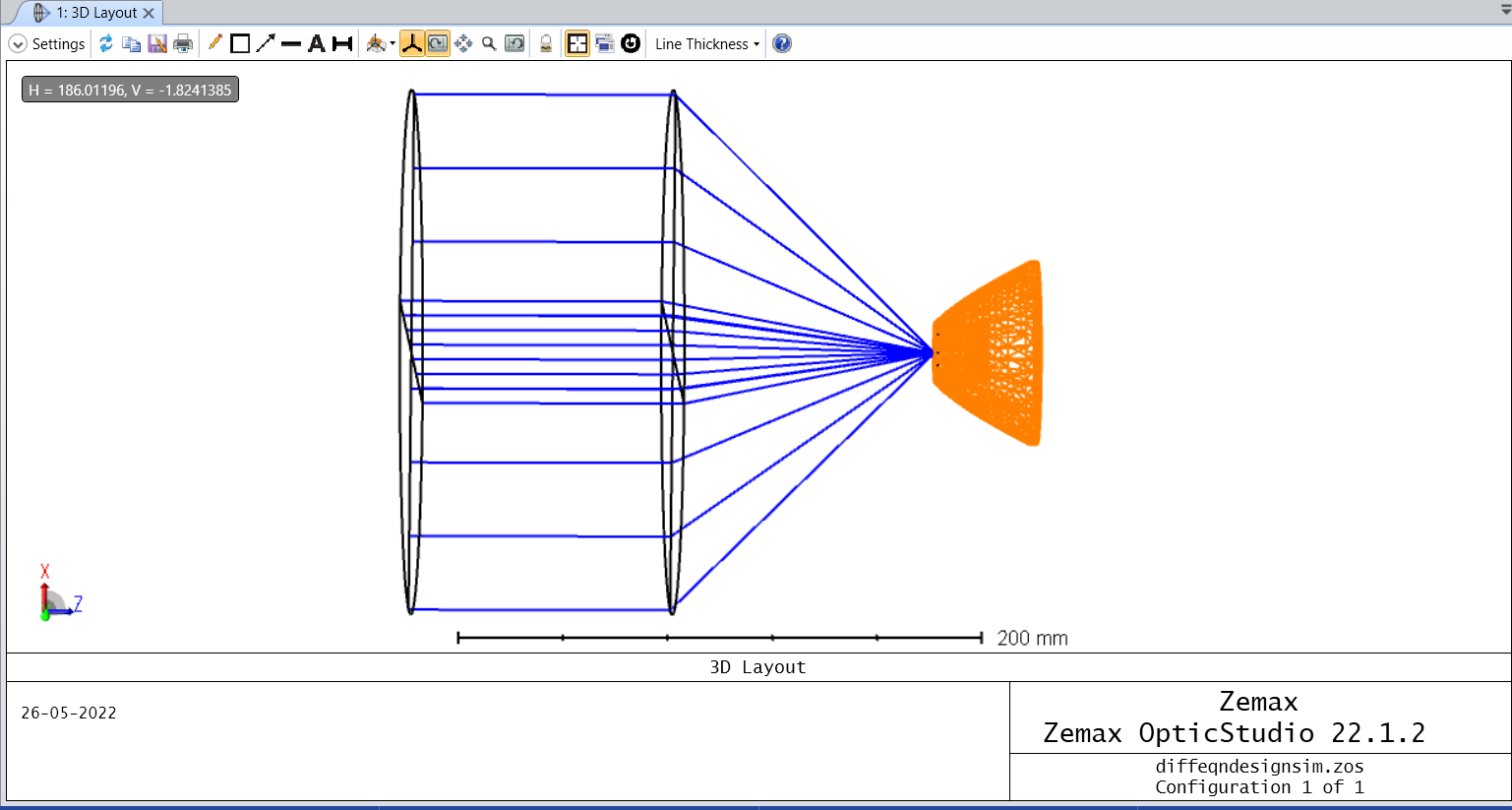
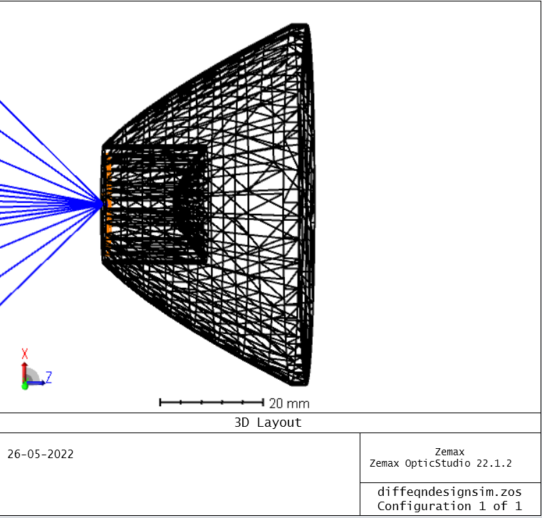
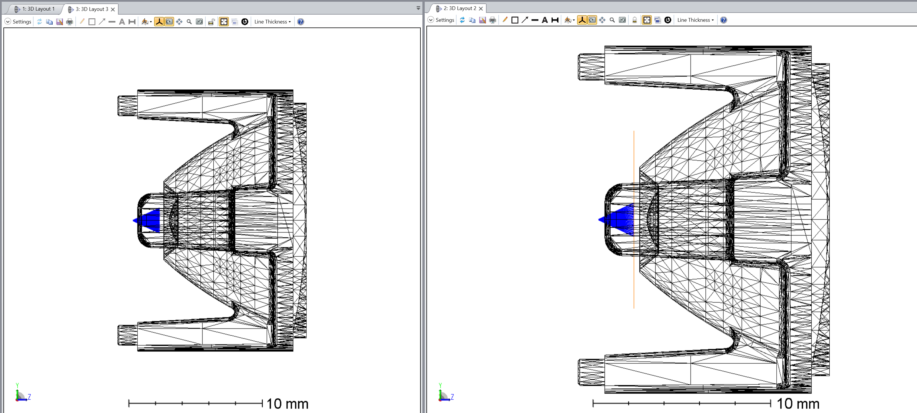
In short, I use the Draw Ports? parameter of the Non-Sequential Component to display the Exit Port. If you set the Draw Ports? to 0 (default) it doesn’t display any port, but if you set it to 2, it’ll show the Exit Port only. My trick is to increase the Semi-Diameter of the surface after the Non-Sequential Component and to toggle the Draw Ports? between 0 and 2 to see where the Exit Port is. Look at the example below:
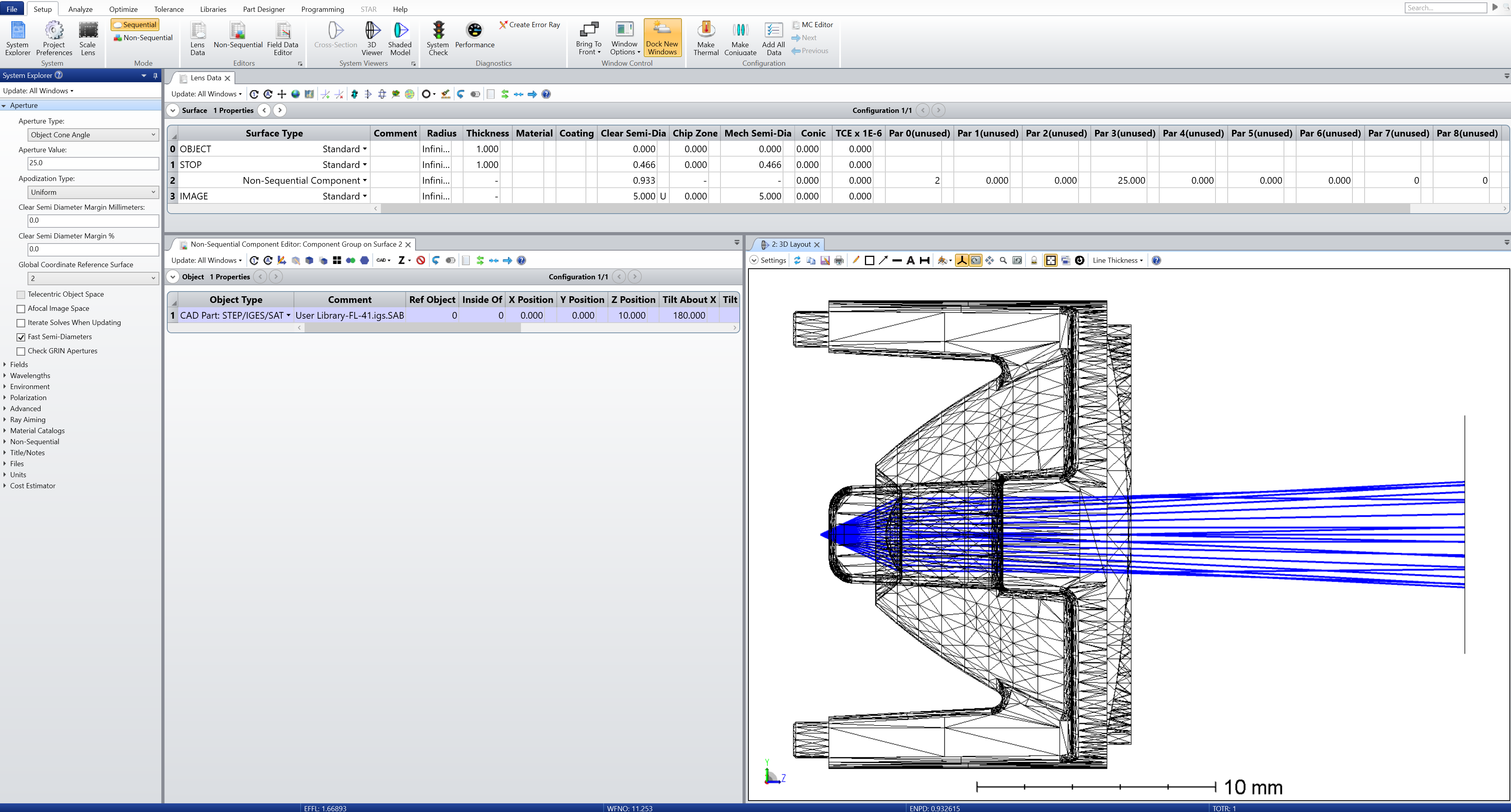
On the left, the Draw Ports? is 0. On the right, the Draw Ports? is 2. As you can see, the Exit Port is the orange surface and is located even before the *.IGES file. It means the rays entre the Non-Sequential Component, but they exit even before reaching the CAD file, and are simply terminated. To avoid this issue, I’ve increased the Z Position of the Exit Port using the parameter Exit Loc Z to 25 in my example. This sends the Exit Port on the other side of the lens and allows the rays to be transmitted.
Let me know if this is clear or if you have further questions on the topic.
Please also note that when defining the Non-Sequential Component material, this is what you are doing (from the Help File):
The glass column of the Non-sequential Component surface is also used to define the "background" material and index of refraction of the media in which NSC objects are placed.
Therefore, I think you want to setup your lens material in the Non-Sequential Component Editor (as shown in my first screenshot).
Just one tip if you want to increase your chances of recieving an answer: try to give as much information as possible, and this includes uploading an example file or an *.IGES file that we could try with.
Your lens looks like a TIR lens, I went ahead and downloaded an *.IGES model here, and I set it up in OpticStudio as follows:
The file is also attached to this post for your reference.
The most important thing to adjust is the position of the Exit Port. If the Exit Port isn’t setup correctly, it is most likely the cause of termination for your rays.
This section of the Help File: The Setup Tab > Editors Group (Setup Tab) > Non-sequential Component Editor > Non-sequential Overview > NSC ray tracing in mixed mode (with entry and exit ports) gives a thorough description of the Entrance and Exit ports.
In short, I use the Draw Ports? parameter of the Non-Sequential Component to display the Exit Port. If you set the Draw Ports? to 0 (default) it doesn’t display any port, but if you set it to 2, it’ll show the Exit Port only. My trick is to increase the Semi-Diameter of the surface after the Non-Sequential Component and to toggle the Draw Ports? between 0 and 2 to see where the Exit Port is. Look at the example below:
On the left, the Draw Ports? is 0. On the right, the Draw Ports? is 2. As you can see, the Exit Port is the orange surface and is located even before the *.IGES file. It means the rays entre the Non-Sequential Component, but they exit even before reaching the CAD file, and are simply terminated. To avoid this issue, I’ve increased the Z Position of the Exit Port using the parameter Exit Loc Z to 25 in my example. This sends the Exit Port on the other side of the lens and allows the rays to be transmitted.
Let me know if this is clear or if you have further questions on the topic.
Please also note that when defining the Non-Sequential Component material, this is what you are doing (from the Help File):
The glass column of the Non-sequential Component surface is also used to define the "background" material and index of refraction of the media in which NSC objects are placed.
Therefore, I think you want to setup your lens material in the Non-Sequential Component Editor (as shown in my first screenshot).