Hi Nadav,
Thanks for posting on the forums!
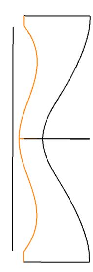
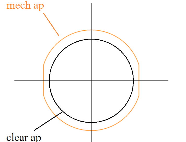
When you use a UDA to define an aperture, you lose the ability to define details like a mechanical semi-diameter or chip zone. So, the UDA will only be able to define out to the geometry you define, which is the mechanical semi-diameter, but it will treat it like a clear aperture.
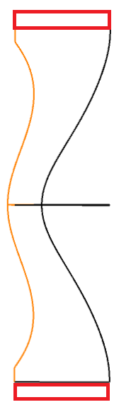
What you could do is to define a dummy surface right before the lens, where the dummy surface has an aperture equal to the clear semi-diameter of the subsequent surface. This would “clip” out potential rays that would land in the non-clear semi diameter region, if that was your intention. This approach is really the only way, as UDA on a sequential surface will remove any mechanical semi-diameter definitions.
If you move to Non-Sequential Mode, though, you could also construct this geometry with something like a Boolean Native object. You could make the lens as normal, then overlap with an Extruded object that contains the UDA file or manually subtract the sides with something like a Rectangle Volume. You can read more about Boolean objects here: How to use the Boolean CAD, Boolean Native and Compound Lens objects, and the Combine Objects tool – Knowledgebase (zemax.com)
Let us know if you have any more questions -- thanks!