Solved

Troubles when using grid sags in OpticStudio

  • 10 September 2021
  • 8 replies
  • 341 views

Hi,

I encounter problems when using grid sags in my optical model. The software become really slow when I try to import a specified grid sag to modelize a mirror.

The importation takes more than a minute, even with a small-sized sag file (64x64).

Even after the sucessful importation, all modules I would use in the software are very slow to compute (shaded model, wavefront, surface sag,..), but I see that the sag is correctly taken into account when I wait for the corresponding mirror sag to be computed, meaning that the .dat file is correctly implemented.

Does someone know the reason why the use of such a grid sag makes the software so slow? Have you got some tips that could help me to accelerate the data processing?

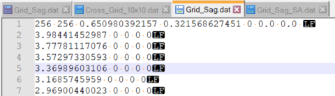
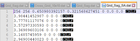
I joined to this question an example of the 64x64 grid sag I mentionned above.

Thank you for your answers.

Pierre


icon

Best answer by Sandrine Auriol 22 September 2021, 12:32

View original

8 replies

Userlevel 6
Badge +2

Hi Pierre

I think that there might be a formatting issue with your file. I’ve opened it in Notepad++ and the lines end with LF:


I have looked at our examples and we end lines with CR LF, so I made the modification:

And it seems to behave correctly now. I have attached the modified file.

Let me know how it goes for you.

Sandrine

Hello,

I’m having a similar issue as Pierre, and I have double checked that my .dat files have the CR and LF at the end of each line. This is a double pass system and I have Afocal image space checked in the system explorer. The system in the Zip has a R156 mm cylindrical surface as a  25x25 grid sag (Cyl25), but I want to use this as launching point to do acylindrical surfaces (WolterP25).

My imports are very quick, but when I try to open analysis such as wavefront map, it takes over 3 hours to generate. The wavefront generated is also very different (over 100 waves of difference) compared to if I were to use a toroidal surface instead of the grid sag (I used this as a double check, but I don’t want to use it in general because I can’t analyze the acylindrical surface). 

Would there be different reason that grid sag would make a system slow down and possibly very inaccurate? I expect some extra time and some error to creep in due to interpolation, especially with this low sampling, but this is excessive to be that.

I would like to approach it this direction, but I’m also open to suggestions of approaching this problem from a different direction. 

Thank you,

Hayden

Userlevel 6
Badge +2

Hi Hayden

Your file formatting seems correct to me. I tested and it takes a really long time too on my side to calculate the wavefront map (I didn’t finish the calculation. I terminated it after 10 minutes). I originally thought it could be improved by using the TrueFreeform surface. I used it to model the surface as a toroidal and then added a grid sag for the remaining values. But the issue is similar.

I looked at our bug records and two of my colleagues reported slow behaviour with grid files. They said that version 19.4 helped. So I tested with 19.4SP2 and it takes 42s to calculate the wavefront map. It is still very long but much better.

The version 19.4SP2 can be downloaded here: https://downloads.zemax.com/Downloads/ZOS19.4_2019-07-31_SP2.exe

Let me know if that helps. I’m going to check with one of my colleagues in case I missed something and if not I’ll check with our developers. I will keep you informed. Have a nice day.


Userlevel 6
Badge +2

Hi Hayden

My colleague had a look at your file and it seems that there is an issue using the Paraxial lenses. If you swap them with real lenses then the problem disappears. Let me know if that can help you move forward.
Although the ray tracing through paraxial lenses is well defined, computing the OPD is more difficult.

Userlevel 7
Badge +3

It may be worth playing with the Mode flag of the Paraxial surface. From the docs:

===

Setting the OPD Mode 

Mode = 0 is very fast and accurate in most cases if the aberrations are not severe. If the Mode = 0, then the OPD computation is based upon the conjugate positions computed by tracing a real parabasal ray. This is preferred for axial optical systems with modest aberrations.

Mode = 1 integrates the actual phase introduced by the surface for each ray traced. Mode = 1 is substantially slower than the other modes, but is generally the most accurate. If the aberrations in the optical spaces on either side of the paraxial lens are large, the paraxial lens OPD computation cannot assume that the lens is working at fixed conjugates for all incoming rays. For these systems, the OPD mode should be set to 1. Mode = 1 can also be used to check if one of the other modes is accurate. If the same OPD results are produced by Mode = 1 as another mode, then the other mode may be used as it will generally compute the OPD much faster.

Mode = 2 assumes that the lens is used at infinite conjugates regardless of the actual conjugates. This option will return incorrect results if the incoming beam is not reasonably collimated.

Mode = 3 is similar to Mode = 0, except paraxial rather than real rays are used. Mode = 3 is only valid for systems with modest aberrations that are well described by first order optical theory.

For maximum OPD computation accuracy, the working F/# of the paraxial lens should be no faster than about F/4, regardless of the OPD mode selected.

===
 

Userlevel 6
Badge +2

Hi Mark

Thanks a lot for your comments. In that case, Hayden is using a Paraxial XY surface so there is only Mode 1.

Hi Sandrine and Mark,

Thank you for taking a look at this. I was able to run this with a set of real lenses and it increased the speed dramatically and I’m able to calculate the wavefront. This helps my analysis tremendously 

With refractive lenses this works great, but for the ultimate problem that I’m solving I would like to use a grid phase in their place (in the place where the paraxial lens is now) do either of you see a potential repeat of this problem with a grid phase surface inline?

Userlevel 6
Badge +2

Hi Hayden

I think you shouldn’t have any problem with the grid phase. The optical path calculation is quite straighforward with a grid phase. The phase adds to the optical path length of the ray. I did a quick try with a grid phase I add and that seems to work well. But any problem, let us know.

Reply