Solved

trace to surface

  • 10 June 2021
  • 6 replies
  • 128 views

Hi!

Is it possible to trace rays from a source to a given plane and then record the x, y, z, A, B, C and 'power' for every ray to a reusable file?  I'd want to reuse this ray file as a spatial source for other geometries. I a not looking for a far field solution (like an IES file), I need to preserve possition and angle of the rays as well as direction.


Bram

icon

Best answer by David 10 June 2021, 23:14

View original

6 replies

Userlevel 6
Badge +4

Hi Bram,


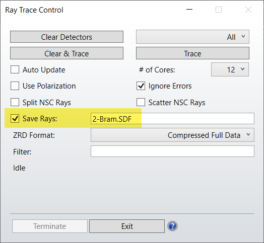
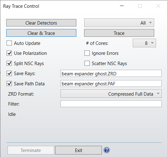
Yes -- very possible. First put an object -- like a detector -- where you want the ray save/origin plane, trace rays and save the rays to a ZRD file:


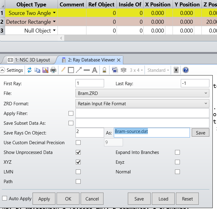
Next open the ZRD file in a Ray Database Viewer, and save the rays on the target object as a DAT file:


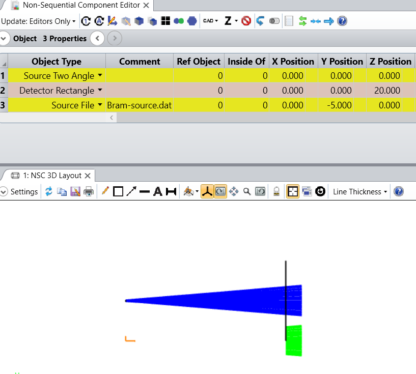
Now that you've saved the rays as a DAT file you can use a Source File object and designate its file as the DAT file you created. The rays will originate from a location dependent on the position of the orignal target object in the original global coordinate system. (If you want the rays to originate from the Source File location in the design which has the Source File, then you can make the original target object the coordinate reference in the original system.)


Best,


David


PS. I attach a ZAR for the example.

Userlevel 6
Badge +2

Hi Bram and David


Thank you David for answering. That is a good technique. You can also do it directly from the Ray Trace control. It will save BRAM.SDF (it works also with the extension DAT) which are the rays on object 2.


Sandrine

Userlevel 6
Badge +4

That's great , Sandrine. Much easier. Maybe a somewhat new option. Or maybe one I just didn't notice when it came out. 

Badge +1

Hello David and Sandrine


If we look at the last lens in a beam expander using in non sequantial mode split rays, we get rays that pass straight and rays that reflact from a convex surface, Is there a way to get on the detector, only a reflacttion rays ?


Thanks  


Yair

Userlevel 6
Badge +4

Hello Yair,


What you are refering to is stray light analysis. Useful information on that can be found in the knowledge article: Introduction to stray light analysis.


What I think you are describing is the rays that ghost from the objective lens and result in contaminating the beam. As an example, I opened the 5x beam expander in the design templates library and converted it to non-sequential. I then ran a ray trace using only 5 rays for illustration. The trace is done with splitting on and saved to a ray database.


I then use the ray database as the input to a layout window and a detector window. Both of these allow that choice in the setup. I also use a filter string of G3&H5 which selects only rays that ghost from object 4 (the objective) and hit object 5 (the detector).


I recommend reading about filter strings in the help system. I also recommend reading about Path Analysis. Path analysis groups rays according to the order in which they strike objects (paths). It reports the power in each path and can create a filter to be used to select particular paths for analysis. The path structure makes it very easy to evaluate and visualze stray light issues.


I attach a ZAR for the example.


Kind regards,


David


Badge +1

Hello David , Thanks for the detailed explanation I know about using filter string, there are not many examples in zemax knowledgebase

Thank you 


Best regard


Yair 

Reply