Solved

Tolerancing of telecentric system

  • 14 February 2022
  • 5 replies
  • 423 views

Badge

Hello, 

I have an object telecentric imaging system and I would like to tolerance its telecentricity.

I have simulated the object moving in z using 2 configurations for the two object positions. 

My idea was to generate a merit function that calculates the magnification for each configuration and ask the difference between the two to remain below a certain value.


Is this good enough or does someone have a better proposition?


Thank you

icon

Best answer by David.Nguyen 14 February 2022, 16:22

View original

5 replies

Userlevel 7
Badge +2

Hi Eirini,


I’m not sure I understand the problem correctly, but for telecentricity, I typically use the chief ray angle for multiple fields with an operand such as RANG.

If your system is telecentric the chief rays should be parallel across the field (on the side where its telecentric).

I setup several RANGs with Px, and Py equal to zero (chief ray) and have Hy or Hx take the values 0.0, 0.5, 0.8, 0.9, for example. Similar to the Gaussian quadrature sampling, if that makes sense.

Take care,


David

Badge

Hi Eirini,


I’m not sure I understand the problem correctly, but for telecentricity, I typically use the chief ray angle for multiple fields with an operand such as RANG.

If your system is telecentric the chief rays should be parallel across the field (on the side where its telecentric).

I setup several RANGs with Px, and Py equal to zero (chief ray) and have Hy or Hx take the values 0.0, 0.5, 0.8, 0.9, for example. Similar to the Gaussian quadrature sampling, if that makes sense.

Take care,


David

Thank you for your answer. 

I had tried that at a certain point but since the system is quite telecentric, the RANG between the fields and configurations was constat due to the decimal point accuracy (I think) so I could not contruct my merit function using the RANG operator.


Best, 

Eirini

Userlevel 7
Badge +2

Hi Eirini,


I’m not sure what you mean with decimal point accuracy. The number of decimals displayed in the Merit Function Editor depends on your Setup..Project Preferences..Editors..Decimals. However, OpticStudio uses the double, 64-bit value for all the calculations, and does so without any loss of precision. You can always check by increasing the number of displayed decimals.

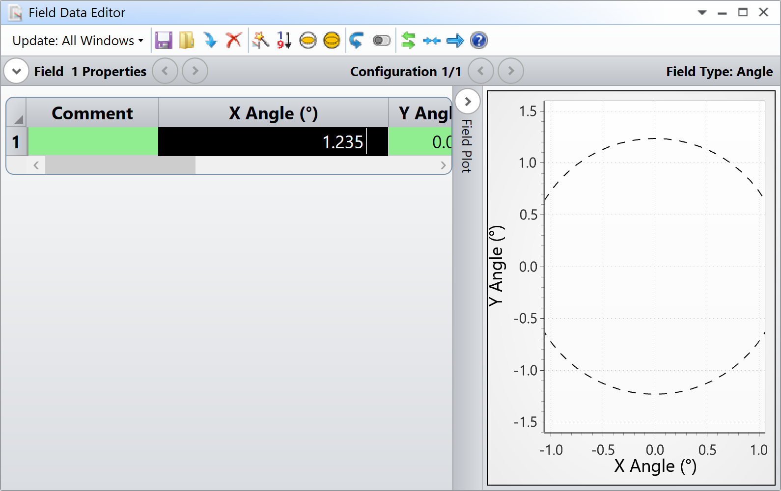
For example, in my project preferences, the decimals is set to 3 (I think it might be the default value). If I type a field angle of 1.23456789, this is what the editor shows:

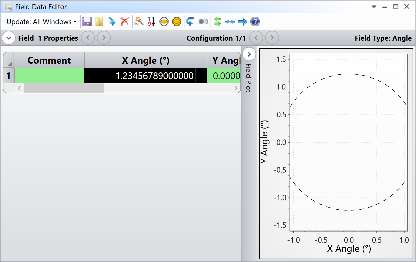
But if I change the number of decimals displayed, this is what the editors become:

And we are limited to 14 decimals, but really OpticStudio keeps the complete 64-bit value in memory.

Does that make sense? Perhaps, you would like to share an example with us for further discussion? If you were seeing a true zero Merit Function, then your system was probably perfectly telecentric.

Take care,


PS: I have used RAID instead of RANG because RAID gives a result in degree that can be compared directly to the field value.


David

Hi David,

since I’m using the Object height as fields, How can I check telecentricity using Hx or Hy values?

I would like to understand which could be the max angle error of the lens I can declare as specification.

Userlevel 7
Badge +2

Hi Ste64,


Hx, and Hy always refer to your field definition, not matter what it actually is. Hx, and Hy are just relative numbers between -1 and 1. If you use an Object Height definition, then the value Hx = 1.0 corresponds to the maximum Object Height defined in the System Explorer. Does that make sense?

Take care,


David

Reply