Tilt image plane

  • 15 February 2021
  • 5 replies
  • 905 views

Hello,


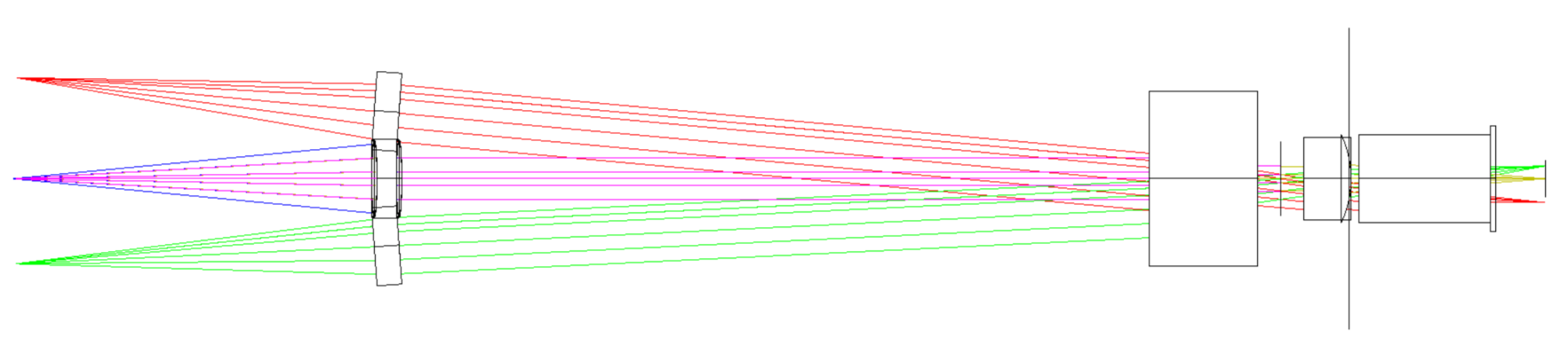
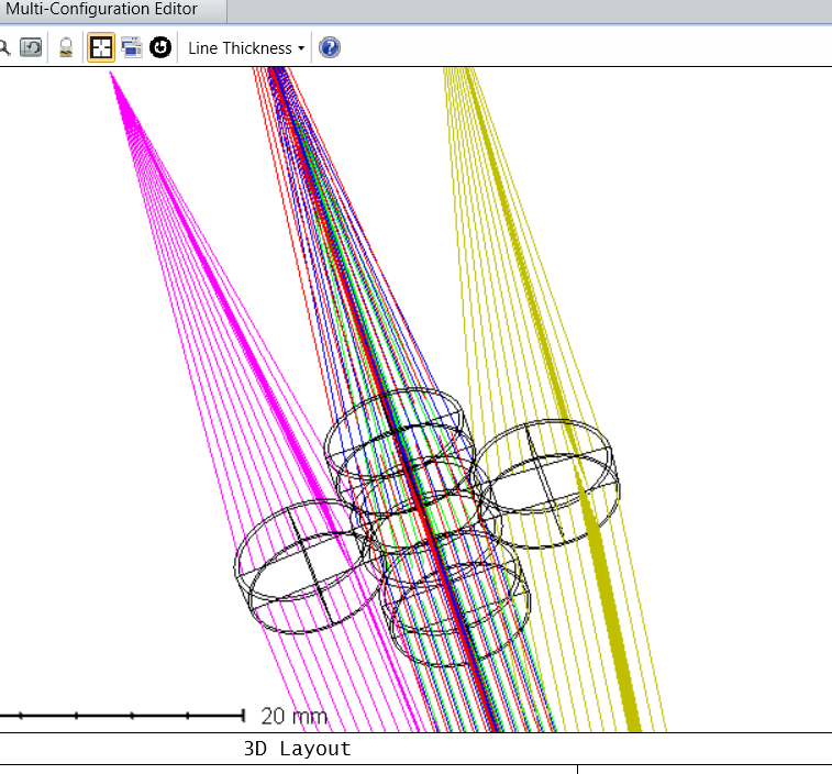
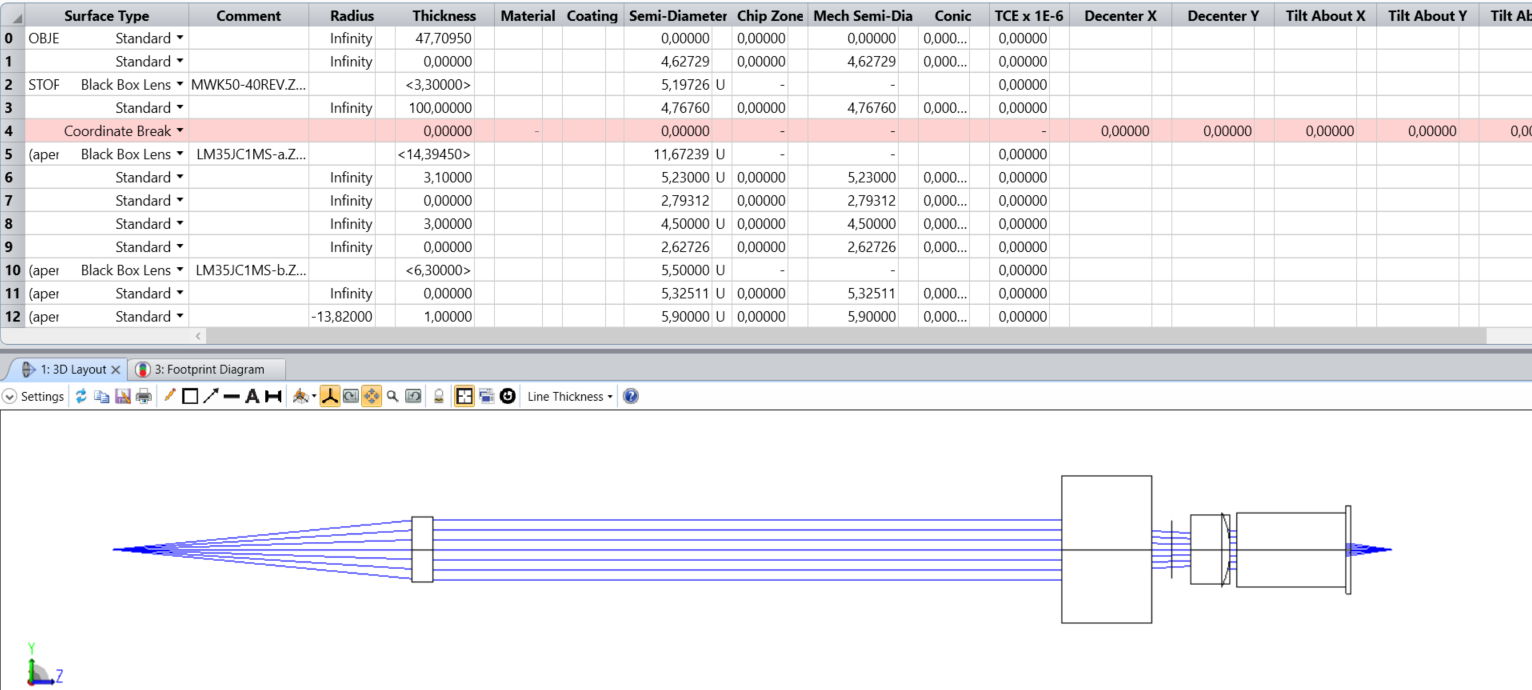
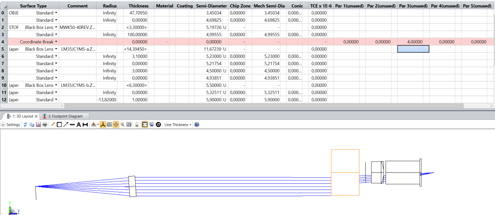
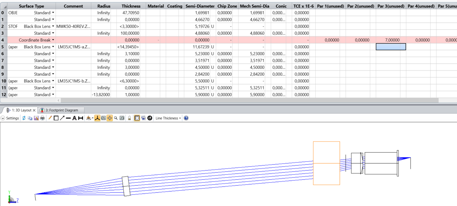
I want to tilt the last part of my system, but I want to tilt the image plane with it. For example, I hav 3 lenses and want to tilt the last two, with the image plane having the same tilt as the last two elements (see image). Is this possible? (I am working in sequential mode.)


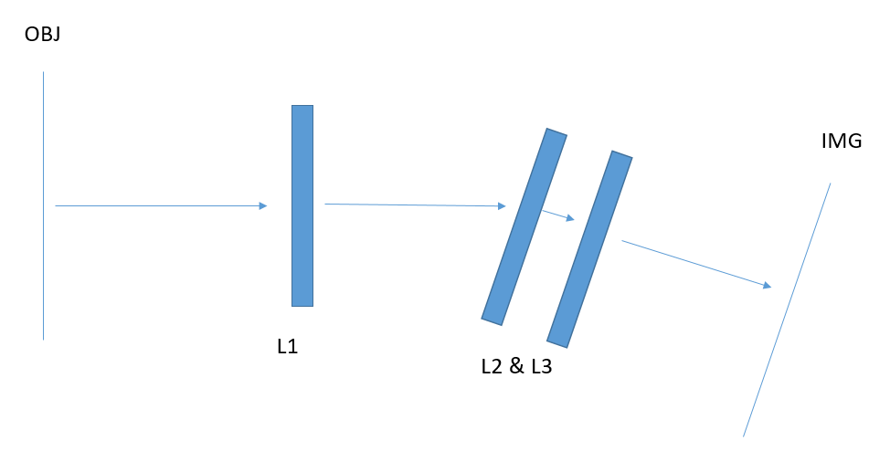
Or is there another way to solve the problem I have? L1 is a collimator, sending collimated light to L2 and L3, and I want to see the effect of sending collimated light to L2 & L3 under different angles. I have done it already using different fields, leaving L1 out and using obj distance infinity, but I want to know if there is a way if I can do it with L1 in the setup.


5 replies

Userlevel 5
Badge +2

Hi Rick,


Thanks for your question here on the forums!


Yes, it is possible to tilt the second part of your system together with the image surface. All you need to do is to add a Coordinate Break surface before the first surface of the L2 lens. This will tilt everything after the Coordinate Break, L2, L3 and the image surface too, as long as you don't add another Coordinate Break to restore the tilt.


You may read more about the Coordinate Break surface in the Help system at:

The Setup Tab > Editors Group (Setup Tab) > Lens Data Editor > Sequential Surfaces (lens data editor) > Coordinate Break


For further references, please check out these knowledgebase articles and forum posts which will give you more explanations and show you use cases:


How to tilt and decenter a sequential optical component · MyZemax


OpticsTalk: Coordinate Breaks - Usage & Applications · MyZemax


Envision 2020 Workshop: Coordinate Breaks · MyZemax


I hope this clears things up a bit, but if you have any further questions, please let us know and we will be happy to help!


Best,


Csilla

Thank you Csilla! This is of great help!

Hello again!


So, the tilting with one coordinate break works more or less. I was also able to tilt it about a certain pivot point. But, for some reason, when for example I tilt +4 about X, I get a point at a different field heigth than a tilt of -4 about X, for a symmetric system... Not sure how to proceed now...


There looks something strange about the tilt, as the red rays converge more to the purple rays at the first non tilted surface than the green rays.


From this image:


It seems that the ray fans are not modelled the same for the two angles.

I did some more testing. I got it working that the ray fans are better by changing the stop surface. But the tilting is still not working perfect.


This is the situation with no tilt:


This is the situation at 4 degree tilt about X:


This is the situation at 7 degree tilt about X:


So I'm not sure that the tilting is working. 

Userlevel 4
Badge +1

Hi Rick,


I've been looking at your system and I can't duplicate everything without your black box lenses to work with. I can duplicate most of the behavior you are seeing outside of the black boxes, though. It looks like you have the global coordinate reference set to surface 5. This is why that lens and subsequent elements are all aligned horizontally. The tilt is still imposed, but just from a difference viewing angle. Instead of a horizontal beam bending down, you have an upward tilted beam bending to horizontal.


It also looks like you are changing the field definitions. At 4 degrees, your field starts the beam at the object sufficiently far up to make it horizontal when aimed at the stop, while at 7 the field is shrunk down a bit, so everything starts and remains at an upward trajectory.


If these are not correct evaluations on my part, it might be valuable for you to open a case so we can look at your actual system files, or at least for you to provide more detail about the settings you are using in the system explorer and properties on the lenses. Please let us know if this answers your questions.


Cheers,


Kevin

Reply