Hi Richard,
I don't believe we have any examples specifically modeling an entire projecter assembly with a DMD, but we do have a few ways to model the DMD with our MEMS sequential surface and non-sequential object.
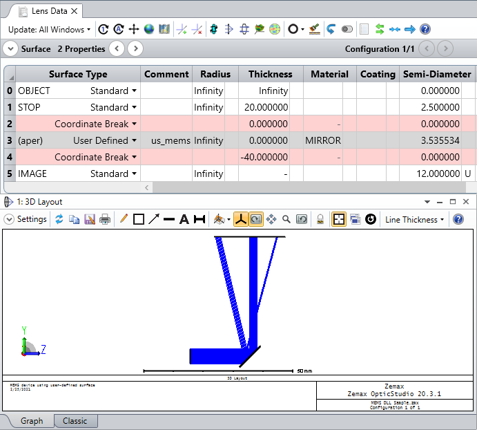
For the Sequential Mode surface, the micro-mirror geometry can be modeled with the User Defined surface type, utilizing the US_MEMS.DLL (the following is from our Help Files at 'The Setup Tab > Editors Group (Setup Tab) > Lens Data Editor > Sequential Surfaces (lens data editor) > User Defined'):
There is a sample file provided in OpticStudio installs that demonstrates the MEMS surface (found at 'C:\ .. \Zemax\Samples\Sequential\Miscellaneous\MEMS DLL Sample.zmx'). It's also attached to this post for convenience!
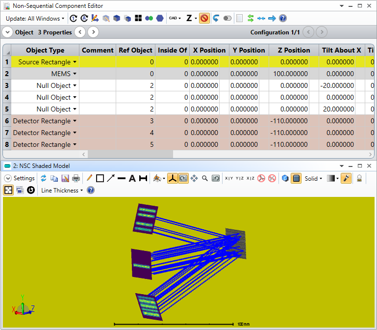
The non-sequential analogue is the MEMS Non-Sequential Object (we also have a sample file for this at '{Zemax}\Samples\Non-sequential\Miscellaneous\MEMS device.zmx'):
What I will mention is that the sequential surface DLL, due to it modeling the ray bending with an idealized flat substrate, doesn't really correctly account for the differences in phase across the surface compared to physically modeling an array of tilted mirrors. Some more discussion can be found at this forum post here.
If you're interested in just the geometric trace results (like a Spot Diagram), the sequential DLL will be sufficient. Accurately computing the wavefront data with a DMD element may require the use of the NSC object in Mixed Mode, though.
Please let us know how these thoughts work out for you!
~ Angel
Thank you Angel!
This was exactly what I was looking for. Let's see if I can make it work.
Best regards,
Richard