System transmission using detectors in non sequential mode

  • 1 June 2020
  • 4 replies
  • 124 views

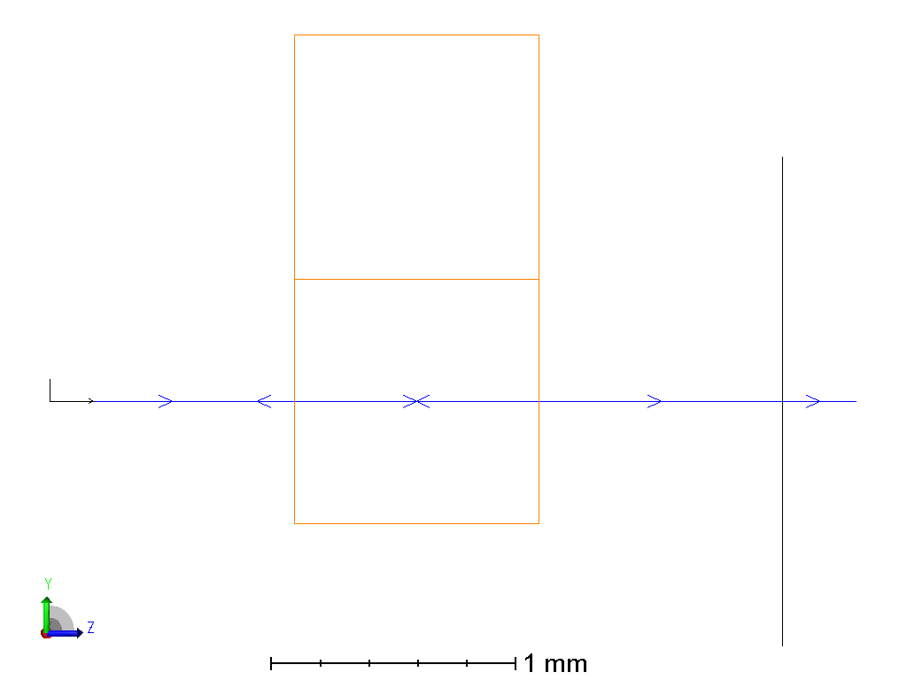
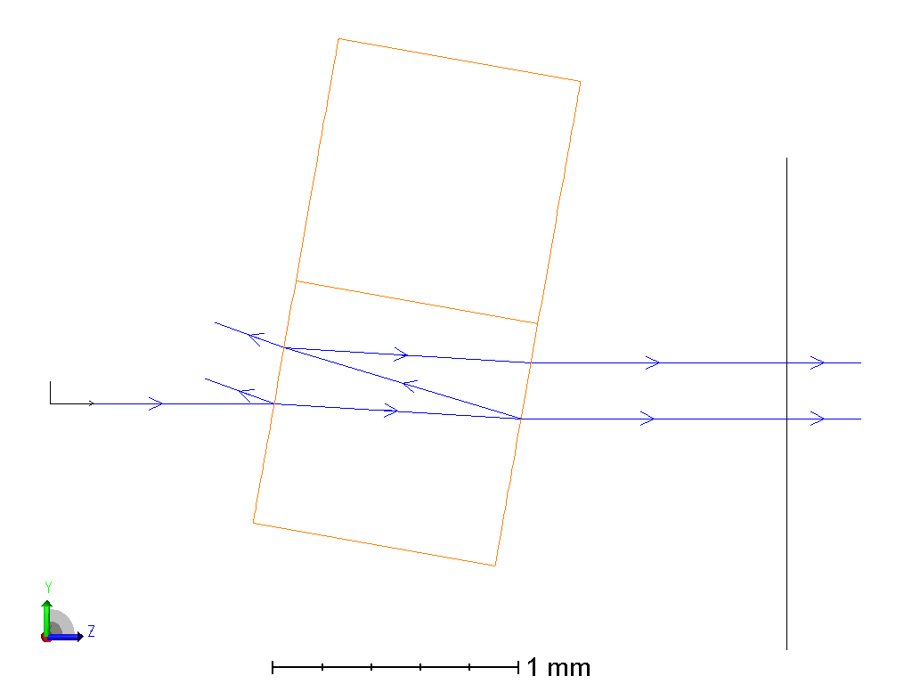
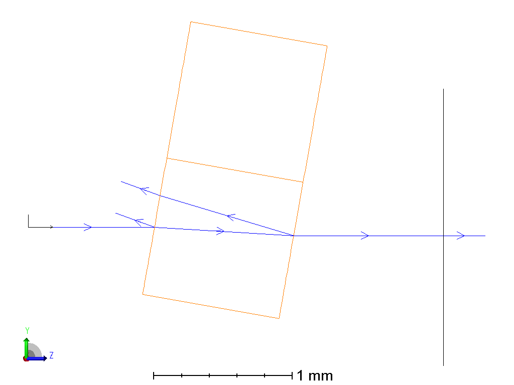
For modeling the transmission of a system I put sensor at the input and another sensor at the output, but I get a transmission which is not compatible with measurement values (it is much lower).   For understanding what is go on, I build the following configuration:   One ray as source, which incide in a BK7 cilinder at zero degrees, and put the detectors before and after the BK7, the first detector records the 100W of the input, but the second record 91.7W  , getting 91.7% instead the 96% I expected.   Indeed, at 'Coating-Transmsision vs angle ' I see that the transmisison for the BK7 is 0.957 at zero degree ( I used 590nm wavlength).  But at the original model I need the overall  transmssion integrated over all angles.   What   I made wrong with the detectors?  There is it a more efficient form to establish the transmission of the system than my detectors aproach?  


4 replies

Userlevel 6
Badge +4

Hi Adrian,


The 'coating-transmission vs angle' is modeling the transmission of the surface, including the effect of any coatings. In this case, the dominant loss is the Fresnel reflection from the air-glass interface. It considers only the surface; bulk absorptions by a thickness is not modeled. The result is the expected ( (n2-n1)/(n1+n2) )^2 for transmission at normal incidence.


In the sequential model, the losses include the effects of bulk absorption (in this case negligible) and the Fresnel reflections at both the entrance (air-glass) and exit (glass-air) interfaces. Since absorption is negligible and transmission near unity, the total transmission is well approximated by the square of the surface transmission, which is what OpticStudio is reporting.


Kind regards,


David

Hi David,


Thank you for your fast response.   It is not clear for me it is the results of the detector after the BK7.  I have a detector before the BK7 which detects 100W total power and a detector after the BK7 window.   The detector after BK7 it  is measuring 91.7%.  ( 91.7W ).  What is the meaning of the value?   I expected to be the transmsion, as you explain, approximatably the square of surface transmisison. 

Userlevel 6
Badge +4

H Adrian,


Here is what I think you have modeled:


It is a BK7 window with a single ray passing through it to a detector. I offset the window so the line in the cylinder is not confused with the ray. The ray passes through two glass-air interfaces on the way to the window.


In the layout below I tilted the window 10 degrees so we could see the Fresnel reflections.


The rrays traced are limited to those with a relative intensity of 0.001 of the original ray, But we see the beginning of the infinite cascade of internal reflections. In the layout below the limit is set to 0.01 so we just see the most significant.losses:


If we consider the original non-tilted case. The transmission through the first surface into the window is 0.9578 as determined by the 'transmission vs wavelength' analysis. This represents a reflection of about 4%. The the transmitted ray then encounters a second glass-air interface as it exits the window. That will also transmit 0.9578. So discounting bulk absorption -- which is negligible -- the total transmission through the window will be o.9578 x 0.9578 = 0.9174.


When I send a 1 watt ray through the window I get 0.9173 measured by the detector.


Kind regards,


David


Hi David,


I see my mistake, I thought  that the transmisison vs angle is the object transmission..


Thank you for your assitance.


Best Regards,


Adrian


Reply