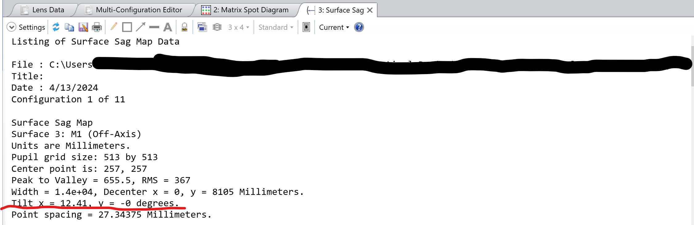
Hi! For off-axis coordinates in the sag map, the center of the sag map corresponds to the center of the aperture on the part, and the angles reported are chosen so that the sag map has zero tilt across the aperture.
You are correct that the aperture is not adjusted in the new, off-axis coordinate system. We made that choice due to the way that apertures are defined in Zemax; apertures are always applied in the Y-Z plane as defined by the local vertex of the surface and then projected onto the part, giving elliptical parts for steeply curved surfaces. Optics tend to have circular substrates, though, so we chose not to adjust the off-axis sag map aperture away from circular.
If you would like an elliptical aperture to appear in the off-axis sag map, just calculate the elliptical aperture shape and apply it to the surface using either the built-in elliptical aperture or the user-defined aperture, depending on how much accuracy you need. Another option would be to oversize the starting aperture, retrieve the sag data, and apply a mask to it.
Best regards,
Erin