Hi Jose!
Thanks for posting on the MyZemax forums. Modeling surface imperfections such as scratch/dig tolerances are a bit challenging in OpticStudio, as the main way to consider general surface imperfections on a system is to understand the ray scattering effects that these imperfections will generate. However, scattering parameters are not able to be specified in the Tolerance Data Editor, nor are surface scattering parameters something that can be defined in the Multi-Configuration Editor (to be able to define different levels of scattering in different configurations, for example). To model different scattering levels in different configurations, I think you'd need to create nearly-identical surfaces, but only with different scatter profiles, and have different surfaces active in different configurations using a Multi-Configuration operand like IGNR/IGNM (you can see an implementation of IGNR at this Knowledgebase article).
The other challenge is that there isn't really a particularly straightforward way to correlate a particular scratch/dig specification with a general scattering effect from that surface, especially since details like placement of the imperfections aren't well-defined in the specification.
In general, there are two approaches you could take to model surface imperfections in your optical model:
- Defining a scatter profile on your surface(s) that will be expected to scatter light from their imperfections
- For information on which scatter models are built-in with OpticStudio is available at the Knowledgebase article here. Since you are in Sequential Mode, the relevant scatter definitions will be the 'Surface scattering models' section.
- Modeling the individual scratches/digs based on your specification
- One way that I have heard about modeling this is using something like the Grid Sag surface. The idea would be to leverage the fact that the surface type is able to take in Standard surface parameters, such as the radius of curvature and conic constant values. However, the surface can read in a .DAT file which will be able to define localized changes in the sag, meaning you could theoretically construct a surface profile that is mostly of your nominal shape, but perturbed in different regions to model the imperfections
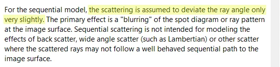
If you need to model these imperfections, the most efficient approach is likely taking the first option. The reason for this is that though the Grid Sag approach can be more straight-forward in modeling the imperfections that you're discussing, it's going to be more resource-intensive to define a grid of sag perturbations as opposed to defining a profile which can generate scattering effects based on probability. That said, in Sequential Mode, we generally recommend that you typically only define profiles that will generate small-angle scattering, as wide-angle scattering typically destroys the relationship of rays entering your optical system and forming an image at the image plane (the following is from our Help Files at 'The Setup Tab > Editors Group (Setup Tab) > Lens Data Editor > Surface Properties > Scattering (surface properties)'):
Since scratch/dig on a surface tends to result in wide-angle scattering effect, though, what I have heard as an approach is to instead consider how much light might get scattered out from the system and treat it as a transmission loss (either as a coating definition in your model, defined in the scatter profile itself, or perhaps applied in post-processing of your data). In addition, a net effect of the this scatter is having a more general 'haze' that shows up on your image plane, meaning it might be more valuable to use the tolerancing routine to perturb parameters other than scattering, and then to consider the image plane contamination that arises from your surface imperfections on the models generated by tolerancing (you can take a look at this article for some ways to save models created during tolerancing). If you absolutely need to have scattering considered while tolerancing is being run, I think you'd need to define that profile initially (perhaps as a 'worst-case' or 'average scattering effect' definition), and let that be the 'nominal' file that you run. I should caution, though, that scattering will make some results like the system wavefront or MTF not as physically meaningful, since again, OpticStudio depends on being able to create a wavefront at the exit pupil of the system to generate these kinds of results, which means only geometric-based results will be relevant.
Please let us know how these thoughts work out for you, and don't hesitate to follow-up if you have any additonal questions here!
~ Angel

