Source object relative to CAD object

  • 17 January 2021
  • 4 replies
  • 68 views

Hi


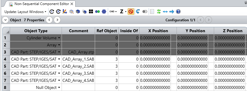
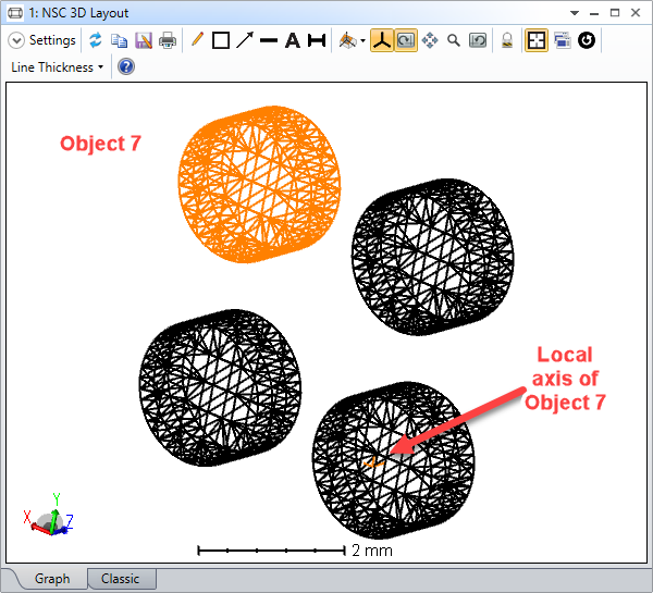
I have loaded a CAD file into OpticStudio and exploded it to get the individual objects.


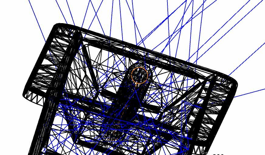
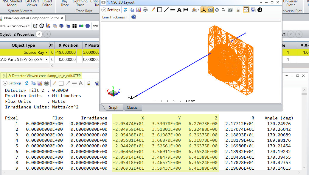
I then created a source tube, which I wanted to place at the same position as one of the exploded components.


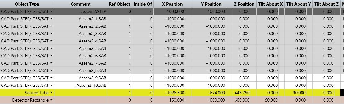
The attached files show the Non-Sequential Editor with the components and my source tube, which I want to be in the same place as object 11.


I had to give it specific X, Y and Z co-ordinates so that it would be in the same place as object 11, but object 11's co-ordinates are just -1000, -1000 relative to the original CAD assembly (object 1).


When I gave the source tube these co-ordinates (also relative to object 1) it appeared in a different position.


As you can see, I had to apply different values to X, Y and Z to get it in the same place.


Can anyone explain why this is?


Thanks in advance.


4 replies

Userlevel 6
Badge +2

Hi Adrian! 


Exploded objects keep the same coordinate system as the assembly. 


For example below, I have exploded a CAD assembly made of 4 cylinder volumes:


As you can see, Object 7 coordinate system is shared with the assembly:


If you make this object as a detector, you can read the coordinates of each facet of the object. Would that help?


Sandrine

Badge

Hi Sandrine.  Thank you for the reply.


This is Jo here - I have been logging in with Adrian's details, but now I can log in as myself!


Can you explain to me how to make an object a detector?  I tried ticking the 'Object is a Detector' box but it didn't make any difference.  And why would doing that make the co-ordinates available?


What I am puzzled about is why the Source Tube object that I created had to be placed in what seems to be an arbitrary position.  Is there any way I can place it relative to the parent CAD object?  I tried to give it co-ordinates that were relative to Object 1, but that didn't seem to work either.


Best Regards


Jo


Userlevel 5
Badge +1

Hi Jo,


Thanks for your follow-up here!


It seems like the issue might be that while you have exploded your assembly into consituent parts, each sub part's local origin may not coincide with your anticipated origin for the part itself. As Sandrine mentioned, all of the sub-components will have their local axes aligned with the origin of the assembly.


You can visualize where the local origin is for Object 11 by using the 'Draw Local Axis' settings in the Object Properties:


In Sandrine's previous post, she showed that the highlighted object was Object 7 (only the top-left cylinder) -- however, the origin for Object 7 is centered on the bottom-right cylinder. So, any object that is placed coincident with Object 7's reference point (by using the Reference Object parameter) will actually be placed coincident with the location of the drawn axis.


As for the workaround, making an object a detector will allow you to view the coordinates of the facets of the object in the Detector Viewer window. The detail to note here is that you can only view Detector Viewer results with objects set as detectors using the Text tab:


It won't quite give you the exact coordinates of your object using this method, though. To get the exact position of your sub-part, I think you'd need to go back into the CAD program that created your assembly and obtain the component's position with respect to the assembly global origin in there.


Please let us know if you have any further questions here, and I hope you have an excellent weekend!


~ Angel

Badge

Hello


Thank  you for that explanation - I have re-checked the co-ordinates that I used, and it now makes sense.


Best Regards


Jo

Reply