At first I should mention that I know the optics words but I am a newborn in ZEMAX. So please if you don’t have time to explain to me in details do not answer!!!
Q1) I would like a to simulate a 2D cross grating with ZEMAX which play the role of a DMD for me. But I don’t know how should I define this surface in ZEMAX?
Can I define a range for the diffraction orders for my simulation? and does it simulate all the diffraction at the same time(in one simulation) or I should tell ZEMAX to simulate each diffraction order separately? I mean, after shining the incident rays into DMD ; Does ZEMAX produce all diffraction rays for me(for example from -2:+2) or I should simulate for -2 then for -1 and so on?
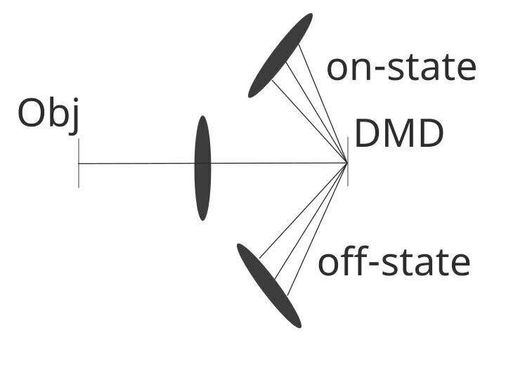
Q2) After that I would like to track the diffracted rays (specifically the -2, -1, 0, 1, 2 diffraction orders in both x and y direction). How can I define a new local coordination system in order to put a new lens on the way of diffraction rays like the image below?
Thanks in advance for your help,
Regards,
Saleh
Best answer by Ethan
Hi @Smousavikhal,
It might be helpful to first start with a simple 1D grating example. I’ve created a file for you to study and adapt. To answer your questions:
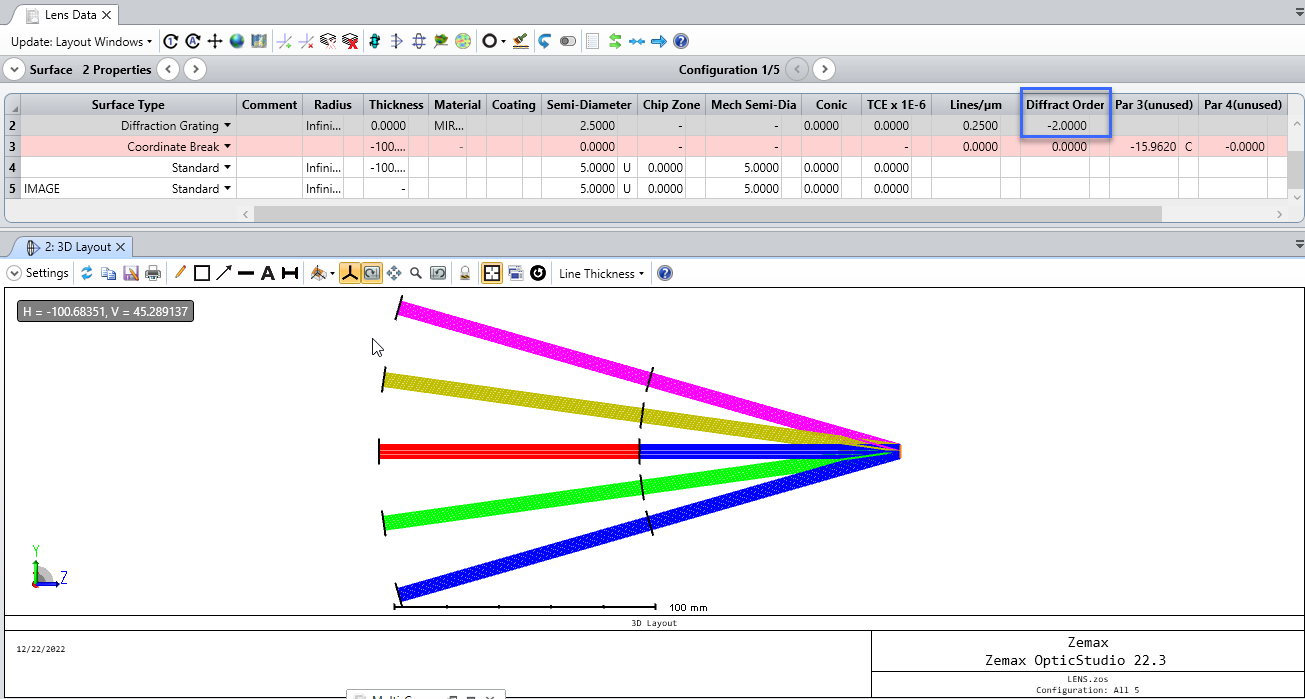
Sequential mode in OpticStudio will only trace one single path (this is not so in non-sequential mode). Therefore, you need to specify the diffraction order, and trace that specific path, one at a time. However, as is done in the attached file, you can set up multiple configurations using the Multi-Configuration Editor, and show them all simultaneously:
By using a coordinate break after the grating, you can rotate the optical axis to match the diffracted order. The lenses and image plane after the grating will then lie along the rotated path automatically. The easiest way to set the angle for the diffraction order is to add a Chief Ray Solve for the angle on the Coordinate Break:
This should get you started on your model, and let us know if you have other questions!