Solved

Simulating Response of Detector By Applying Directivity Constraint

  • November 7, 2023
  • 2 replies
  • 157 views

Hello,

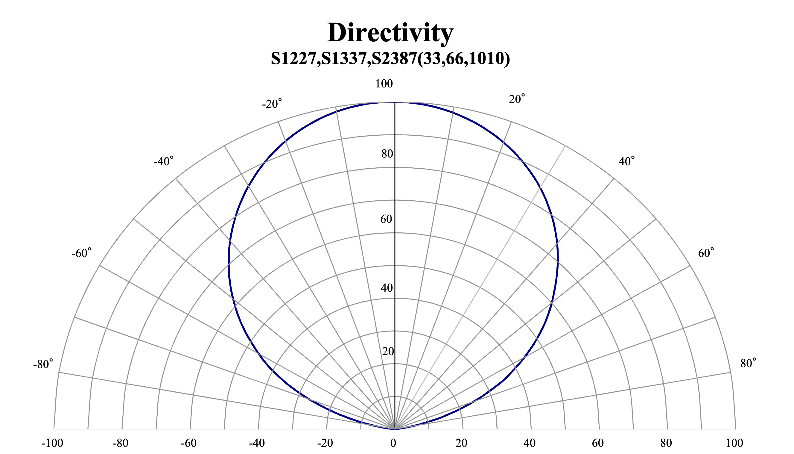
For a silicon photodiode detector, there’s a given Directivity plot that describes the amplitude change in amount of light that the detector sees at a specific angle relative to the normal axis.

I would like to know how to apply this Directivity for a Detector Rectangle object in Non-Sequential Component mode. 

The results of the simulation are meant to show how much light the photodiode fails to detect due to non-collimated light.

I’ve attached ZAR of a simple source gaussian non-collimated light onto a detector rectangle.


Best answer by Jeff.Wilde

You might consider using a thin mask (rectangular volume) placed in front of your detector.  You could construct a TABLE coating to put on one surface of this mask in order to mimic your directivity curve.  This related post may be of some help:


Regards,

Jeff

2 replies

Jeff.Wilde
Luminary
Forum|alt.badge.img+3
  • Luminary
  • 518 replies
  • Answer
  • November 7, 2023

You might consider using a thin mask (rectangular volume) placed in front of your detector.  You could construct a TABLE coating to put on one surface of this mask in order to mimic your directivity curve.  This related post may be of some help:


Regards,

Jeff


  • Author
  • Infrared
  • 13 replies
  • January 27, 2025

As a follow up, is there a way to generate a distribution map/list/values showing representation of incident angles of rays to the detector normal surface? I want to be able to plot a histogram distribution of incidence angle of the detector surface.