Hi all, in an NSC system, I need to obtain a precise x and y luminance value on the color detector, I know the transmittance curves of the material to be crossed and consequently created the glass, I set a merit function where I search for the desired x and y values. I have created a radial source to which I would like to set the x and y emission values according to CIE1931 as variables. In the past, to find the scatter values to apply to a given HPA material, I used the parameters of the multi configuration editor. Is it possible to use the same methodology?
Thanks a lot to everyone.
Best answer by MichaelH
Hi Luca,
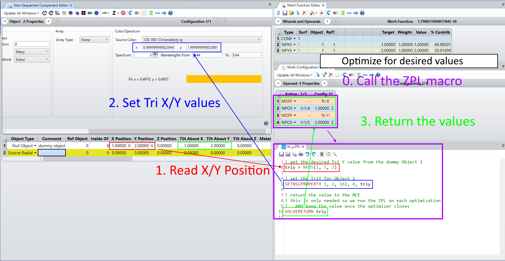
There is a very convoluted way of setting the Tri X and Tri Y values as variables but you have to use a mix of the MCE and 2 ZPL macros. The thought process is as follows:
Use a dummy object to control the TriX and TriY values (use X Position and Y Position); this dummy surface will be the variables the MFE will optimize
Use the MCE with NPOS 1/1/4 & NPOS 1/1/5 to read in the X Position & Y Position in the MCE; these cells will have ZPL solve on them...the ZPL solve will:
read in the X/Y Position using NPOS
use SETNSCPROPERTY with 181/182 to set the Tri X & Tri Y on the Source Radial
return the Tri X & Tri Y value with a SOLVERETURN (this can be any value but you have to have a SOLVERETURN so might as well be the actual Tri X/Y value)
Use the MFE with NPXV & NPYV to target the desired Tri X and Tri Y value
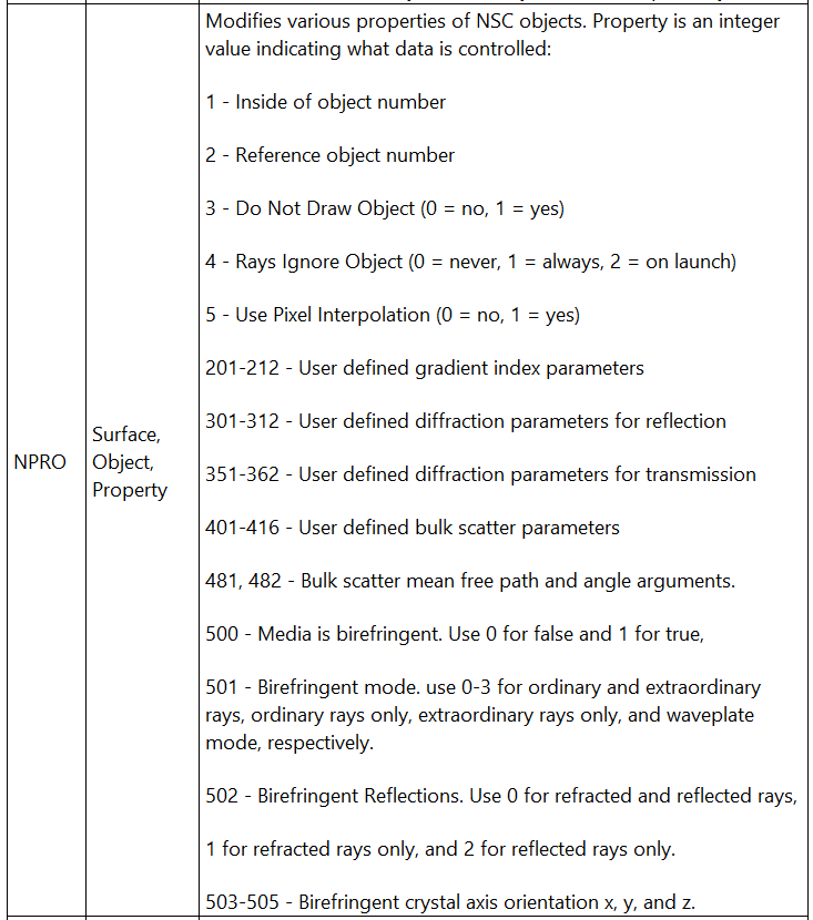
The properties of the objects can be called in the multi-configuration editor using the NPRO keyword:
Unfortunately, the source properties are not available there.
In one of our examples, we had different sources with different wavelengths and we were optimizing on the source power. I don’t know if that could be an option for you.
There is a very convoluted way of setting the Tri X and Tri Y values as variables but you have to use a mix of the MCE and 2 ZPL macros. The thought process is as follows:
Use a dummy object to control the TriX and TriY values (use X Position and Y Position); this dummy surface will be the variables the MFE will optimize
Use the MCE with NPOS 1/1/4 & NPOS 1/1/5 to read in the X Position & Y Position in the MCE; these cells will have ZPL solve on them...the ZPL solve will:
read in the X/Y Position using NPOS
use SETNSCPROPERTY with 181/182 to set the Tri X & Tri Y on the Source Radial
return the Tri X & Tri Y value with a SOLVERETURN (this can be any value but you have to have a SOLVERETURN so might as well be the actual Tri X/Y value)
Use the MFE with NPXV & NPYV to target the desired Tri X and Tri Y value
Excellent I would say, I can integrate this workaround into my system and make it look for the appropriate values of emission x and y to obtain the chromatic coordinates of luminance on my target.