I am trying to optimize a lens prescription based on RMS Spot Radius at a specific distance.
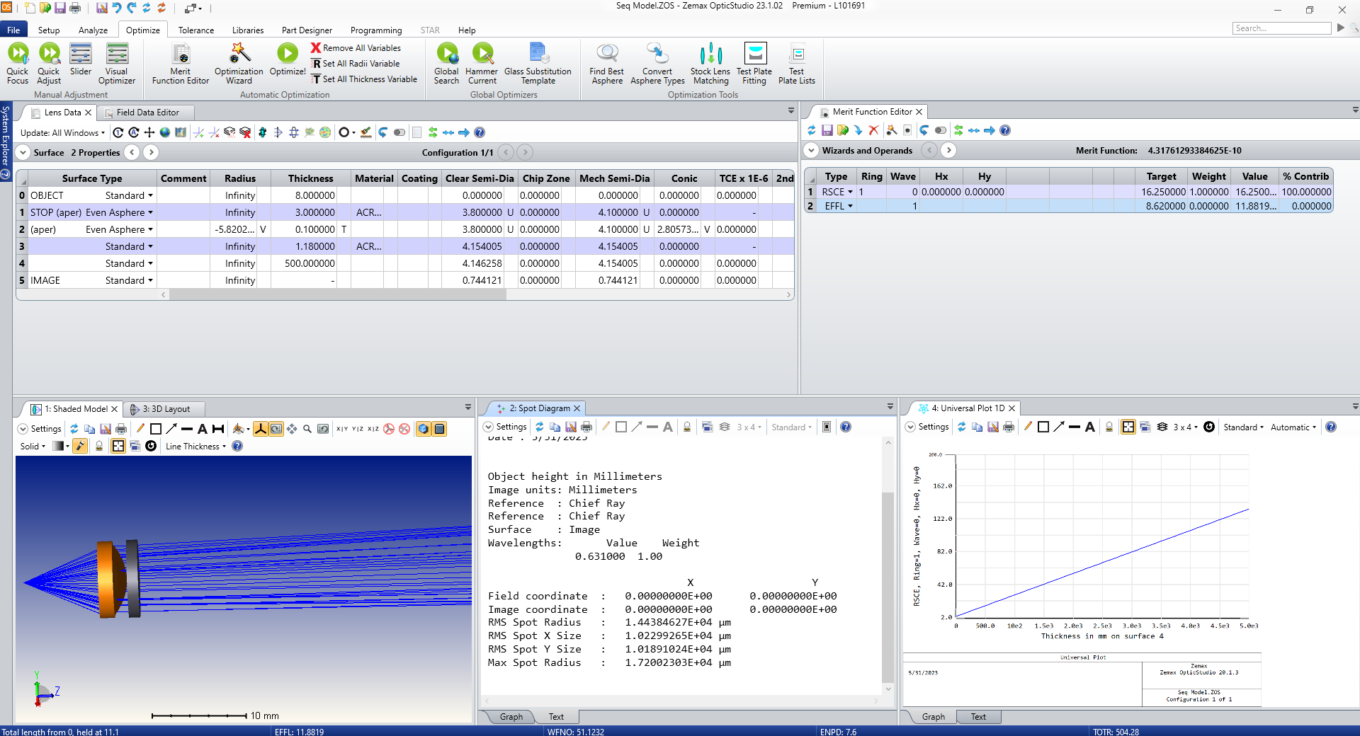
Set the image plane to 500mm, in the merit function I use the operand RSCE and target RMS Spot Radius to 16.25mm.
In Spot Diagram I get a completely different output for RMS Spot Radius.
Am I missing something here?
Best answer by David.Nguyen
Hi Begad,
RSCE is returning the RMS Spot Radus in lens unit, which is mm by default. Therefore, RSCE reports 16.25 mm, whereas your Spot Diagram reports 1.44E+4 um or 14.4 mm, which isn’t vastly different. The remaining difference is probably stemming from your Ring setting in RSCE. Can you try increasing from 1 to, say, 5 or 6 rings?
RSCE is returning the RMS Spot Radus in lens unit, which is mm by default. Therefore, RSCE reports 16.25 mm, whereas your Spot Diagram reports 1.44E+4 um or 14.4 mm, which isn’t vastly different. The remaining difference is probably stemming from your Ring setting in RSCE. Can you try increasing from 1 to, say, 5 or 6 rings?
Thank you for the quick response. I did increase the number of rings but I still don’t understand why don’t both the spot diagram and RSCE match? Is there something about them that is different?
Yes, I think there’s a difference in the way the rays are sampled for each method. In the Spot Diagram, the Help File about the Density setting reads:
Ray Density The Ray Density specifies the number of Hexapolar Rings to be traced if a Hexapolar or Dithered Pattern is selected, or the Number of Rays across the Width and Height if a Rectangular Pattern is selected. The more Rays traced, the greater the accuracy of the RMS Spot Radius, although the computation time increases. There are 6 Rays in the first Hexapolar Ring, 12 in the second, 18 in the third, and so on. The Ray Density Minimum Value is 3.
For RSCE, you only have a ring parameter for the Gaussian quatradure (no arm parameter like in the Merit Function Wizard), and I’m not completely sure how the two approaches to sample the rays correlate with one another:
RSCE
RMS spot radius with respect to the centroid in lens units. This operand uses a Gaussian quadrature method that is accurate for systems with unvignetted circular pupils. Ring is used to specify the number of rings of rays traced. If Wave is zero; then a wavelength weighted polychromatic calculation is performed; otherwise, the specified wavelength number will be used. See “Hx, Hy, Px, and Py”.
Can you also try to increase the Spot Diagram Ray Density and check if the two measurements come closer? Also how different are they now?
Is it possible for you to share your file? You can go in OpticStudio and press File..Create Archive. Then, put the *.ZAR file into a *.ZIP (you should be able to right-click the *.ZAR file and press Send to..Compressed folder) and upload the *.ZIP here.
The RS** operands use Gaussian quadrature, but the spot diagram just uses the data from the specific rays it has traced. You can expect them to be close, but not exact. As you increase the ray density in the spot diagram it will tend towards the RS** operands
The RS** operands use Gaussian quadrature, but the spot diagram just uses the data from the specific rays it has traced. You can expect them to be close, but not exact. As you increase the ray density in the spot diagram it will tend towards the RS** operands
Thank you for the response.
For some reason I can no longer get it to be close to my 16.25mm
In this post here you can see that it wasn’t converging towards the 16.25mm target. Any idea why?
I took a quick look at your model and immediately see a few issues.
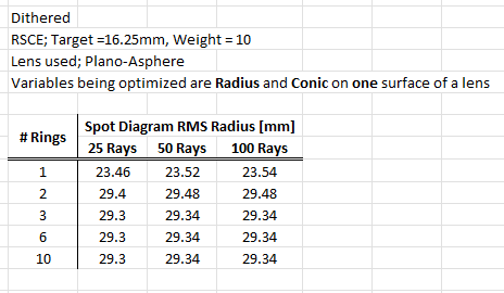
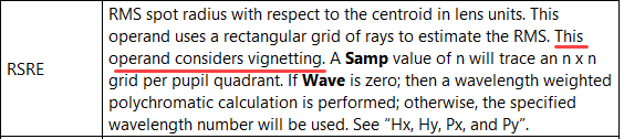
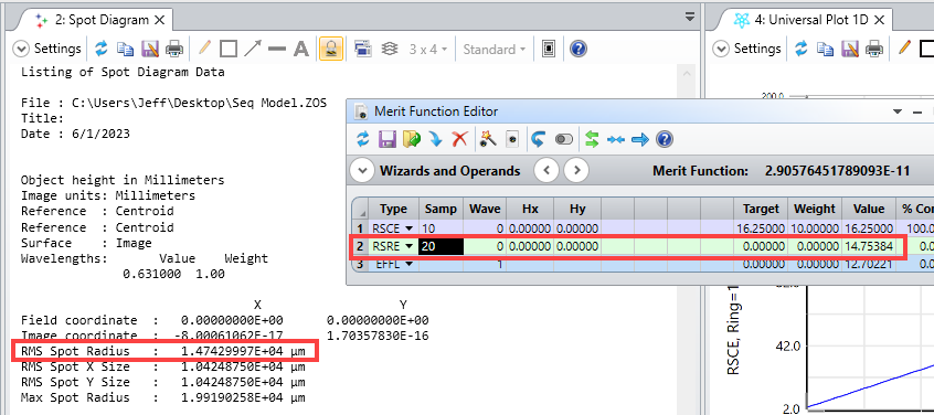
First, some rays are being vignetted by the second lens surface. The RSCE operand neglects this vignetting (and assumes all rays make it to the image plane), while the spot diagram analysis does take vignetting into account. In this particular case, a better spot-size operand is RSRE as it will use a rectangular grid of rays in the pupil and also takes vignetting into account.
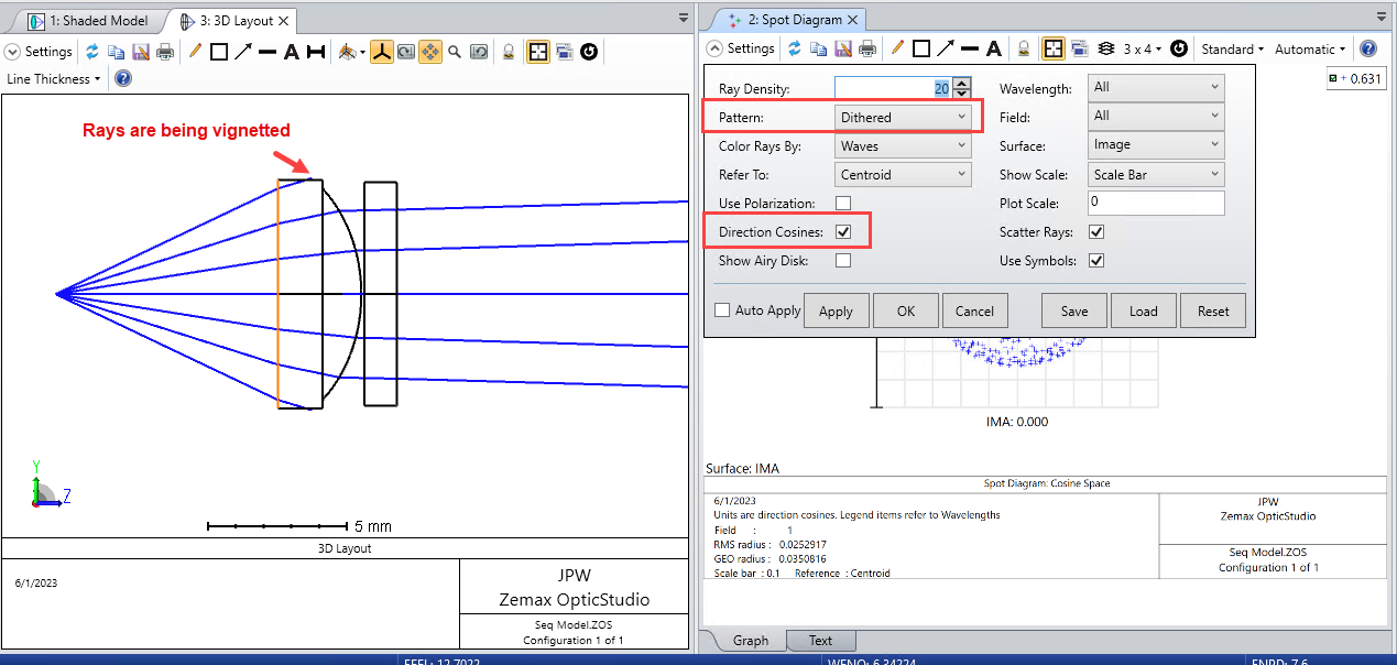
Second, your Spot Diagram settings need to be changed. You have the Direction Cosines option checked, which displays the spot in angle space and reports the spot size in direction cosine space. Also, for proper comparison with RSRE you should use a Square ray pattern, instead of Dithered, when generating the spot diagram. The ray density should be the same as that used for RSRE.
If you make these changes, you will see a much better comparison:
The two values are not exactly the same, most likely because the Spot Diagram and RSRE operand use slightly different rectangular ray patterns (if I recall correctly, there is a small shift offset between the two), but they are very close.
Regards,
Jeff
PS: I should add that for optimization purposes, if vignetting is negligible, then the operands that use Gaussian Quadrature pupil sampling (such as RSCE and RSCH) are preferred as they provide a more optimal sampling compared to a rectangular grid (same degree of accuracy with fewer rays).
Thank you very much for the response. I actually messed around a little with RSRE and couldn’t get a match but it makes sense that is because I had directional cosine and dithered set in my spot diagram.
I will test all the changes you suggested tomorrow, and post here!